Inverter board (PWB2 (F2040-8))
1 Remove the top cover.
2 Remove the front and side
panels.
3 Remove the control board
(PWB1).
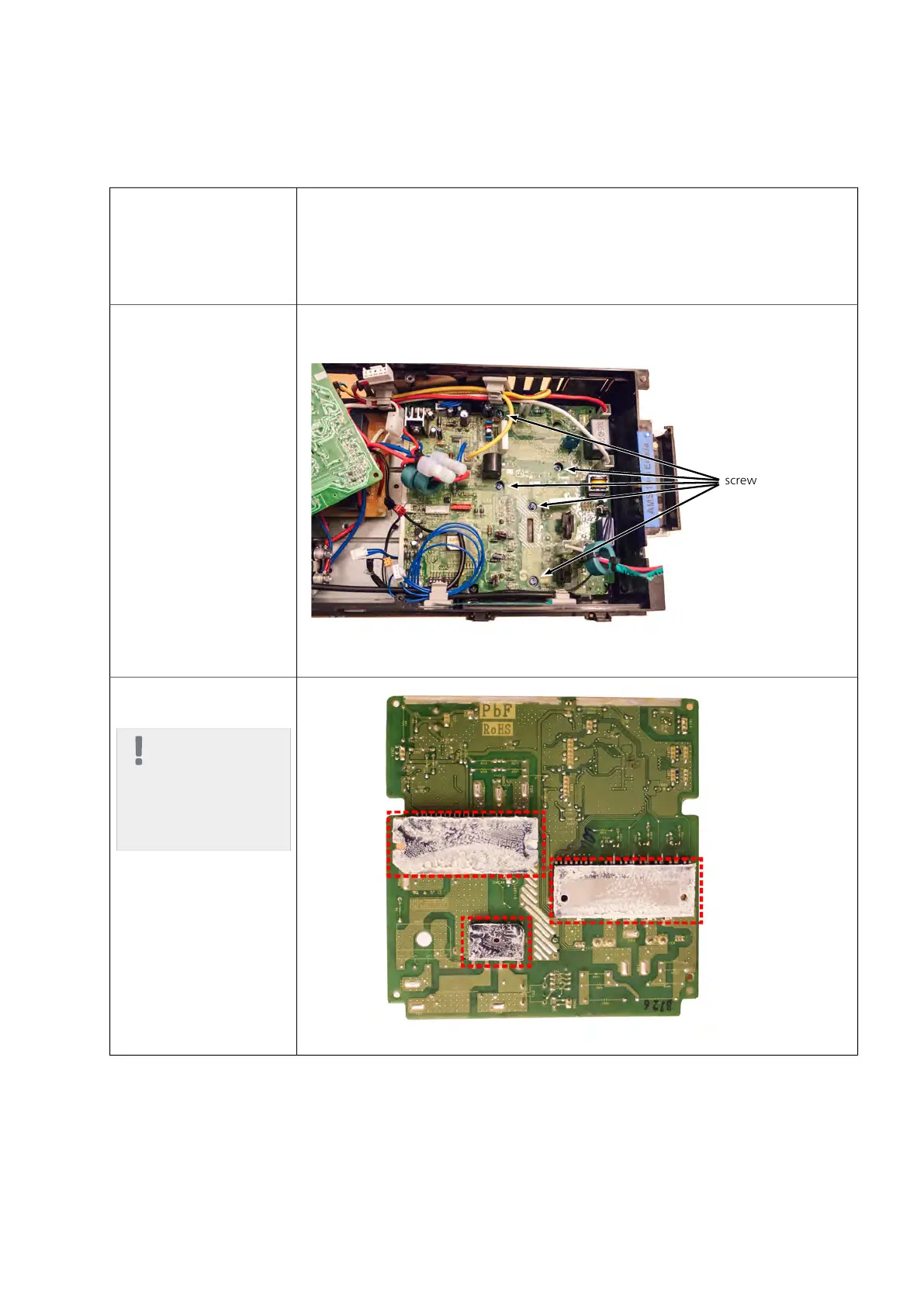
4. Disconnect the cables on
PWB 2.
5. Remove the five screws,
remove the board.
6. Assembly takes place in
the reverse order.
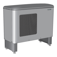
NOTE
New heat transfer
paste must be ap-
plied to the three
contact surfaces of
the cooling flange.
NIBE™ F2040Chapter 7 | Component replacement90