General information for the installer10
FIGHTER 1120
Current regulations require the heating installation to
be inspected before it is commissioned. The inspec-
tion must be carried out by a suitably qualified person
and should be documented. The above applies to
closed heating systems. If the heat pump is replaced,
the installation must be inspected again.
FIGHTER 1120 is placed on a firm base, preferably a
concrete floor or foundation. FIGHTER 1120 should
be setup with its rear against an outer wall in a
scullery or similar type of room to eliminate noise
problems. If this is not possible, avoid placing it
against a wall behind a bedroom or other room where
noise may be a problem. Wherever the unit is located,
any wall that backs on to a bedroom should be fitted
with sound insulation. Route pipes so they are not
fixed to an internal wall that backs on to a bedroom or
living room.
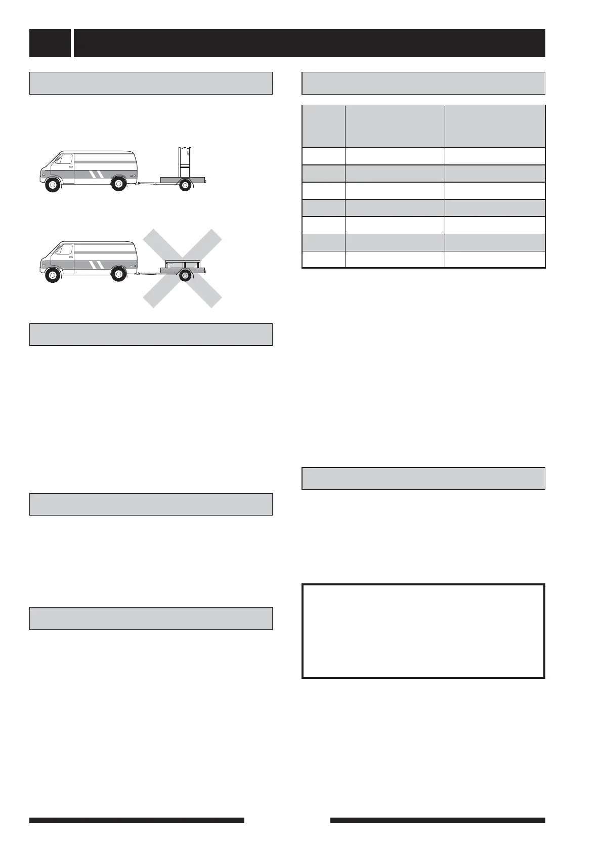
The FIGHTER 1120 must be transported and stored
upright and dry.
Transport and storage
Installation
Guideline values for collectors
Inspection of the installation
For use with 40 x 2.4 PN 6.3 PEM hose.
The length of the collector hose varies depending
on the rock /soil conditions and on the heating sys-
tem, i.e. radiators or floor heating.
Max length per collector should not exceed 400 m.
Where there is more than one collector, they must be
connected in parallel, with a means of adjusting the
flow.
The hose should be buried at a depth of about
1 metre and the distance between the hoses should
be at least 1 metres for surface soil heat.
For several bore holes, the distance between the
holes must be at least 15m.
If required FIGHTER 1120 can be docked to an exter-
nal unit with its own heating controls. FIGHTER 1120
then delivers heat up to a fixed temperature level. This
is called “fixed condensing”. See docking option 4. To
set the correct parameters for fixed condensing see
“Docking - option 4”. The heat medium pump does not
need to be changed.
See the instructions for the external units for how to
regulate the room temperature.
The outside temperature sensor has no function with
this option, but it should be connected to prevent error
messages appearing on the display. There is no need
to install the sensor outside.
Heat production is usually controlled on the “floating
condensing” principle. This means that the tempera-
ture level needed for heating at a given outside tem-
perature is produced on the basis of values taken from
sensors for outside temperature and flow temperature
(see docking options 1 - 3).
Fixed condensing
Floating condensing
NOTE!
Enter the selected values on page 2
in this Installation instruction. The
details are important for
service work.