3 – English
English
ECSBus output One output with maximum load of 10 ECSBus units (1 ECSBus corresponds to the consumption
of a pair of photocells)
SbS input For normally open contacts (closing of the contact triggers the Step-by-Step (SbS) command)
Stop input
Stop command)
Radio aerial input
Max. cable length
m (observe the warnings regarding minimum gauge and type of cables)
Ambient operating temperature -20°C ... +55°C
Assembly -
Protection rating IP44
Dimensions / weight 248 x 216 h 305 mm / 7.5 kg 248 x 216 h 305 mm / 7.5 kg
Possibility of remote control Using ECCO5... transmitters, the control unit is able to receive one or more of the following
Memory capacity Up to 250 transmitters, if memorised in Mode 1 – 250 keys, if memorised in Mode 2
ECCO5... transmitter range From 50 to 100 m. This range can vary if there are obstacles or electromagnetic disturbances
Programmable functions
Pedestrian opening type selectable in 4 modes
Obstacle detection system motor force, 4 selectable levels
Step-by-Step (SbS) command operation selectable in 4 modes
Self-programmed functions Self-detection of devices connected to the ECSBus output
Self-detection of the gate length and calculation of the deceleration points
3.4 - PRE-INSTALLATION WORKS
Consult Fig. 3
a standard and customary layout.
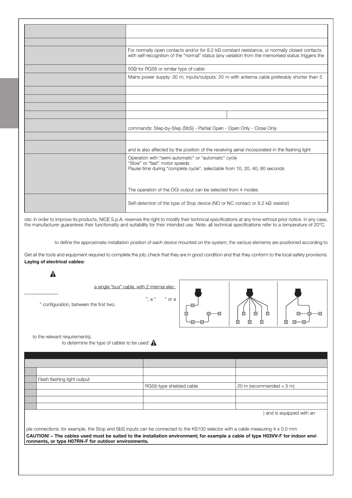
01. Observe Fig. 3 to understand how the various devices should be connected to the control unit and which terminals should be used for each con -
nection.
Only devices adopting the same technology can be connected to the ECSBus .
The ECSBus system allows for connecting multiple devices together using,
between one device and the next, -
trical conductors .
The connection between the devices can have a “ cascade star
“mixed
cascade star combined
02. Observe Fig. 3 to understand how to position the electrical cables in the environment (it is advisable to draw on paper a similar layout, adapting it
03. Read Table 1
each cable must not exceed the stated maximum length.
TABLE 1 - Types of electrical cables (see Fig. 3)
Connection Type of cable Maximum admissible length
A Power supply 3 x 1.5 mm
2
(not supplied) 30 m *
B
2 x 0.5 mm
2
20 m
C Radio aerial
D ECSBus Input / Output 2 x 0.5 mm
2
20 m **
E Stop input 2 x 0.5 mm
2
20 m **
F SbS (Step-by-Step) input 2 x 0.5 mm
2
20 m **
* it is possible to use a power cable longer than 30 m, provided that it has a larger gauge (for example, 3 x 2.5 mm
2
earthing device, near the automation.
** For the ECSBus cables and the Stop and SbS inputs, it is also possible to use a single cable with multiple internal conductors, to group multi -
2
.
-