11 – English
English
01. On the control unit press and hold button P2 (Fig. 25 ) for at least 3 seconds then release it.
02.
switches o. I f instead it ashes, it means that there is some error – see Chapter 10 .
03. After adding or removing devices, the automation must be tested again (Par. 6.1).
Aerial
P4
L4 L3 L2
P3 P2
Sb S
L1
P1
25
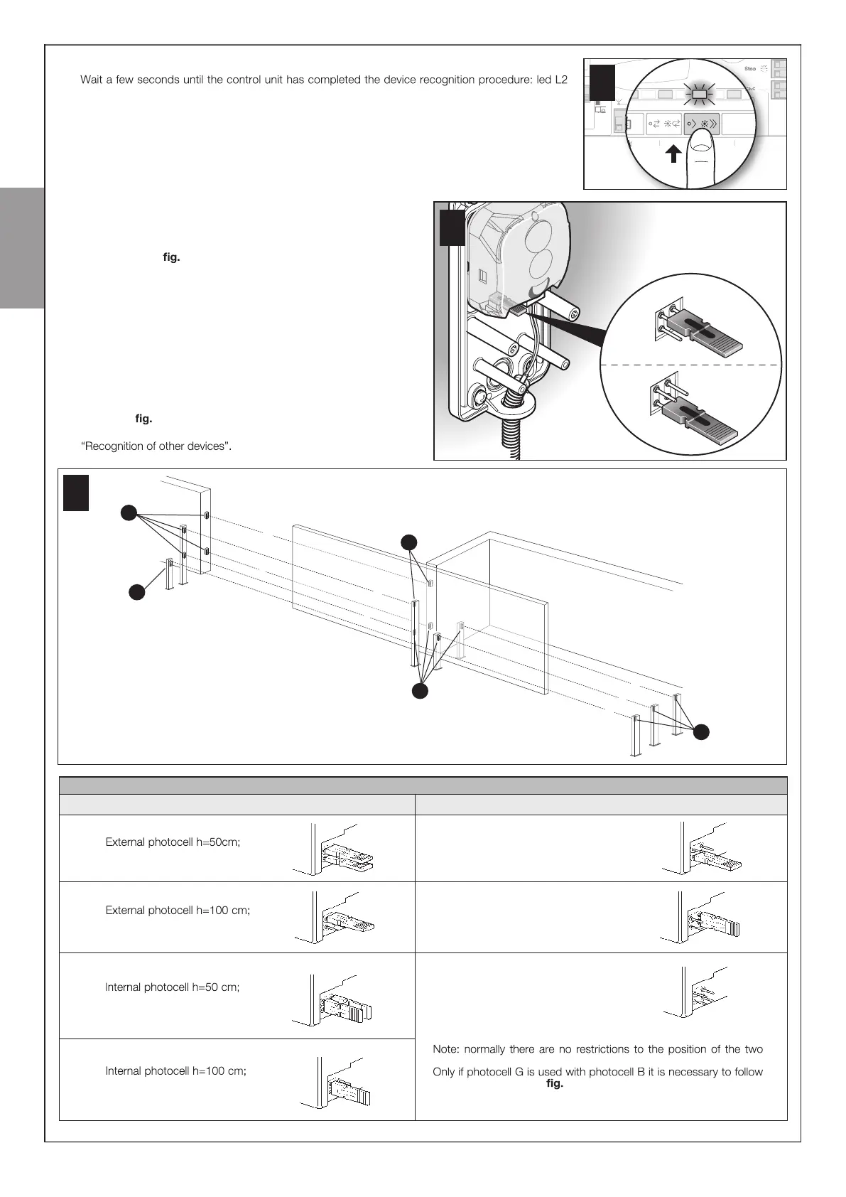
9.2 .2 - Adding optional photocell
IAdditional photocells to those supplied with the FILO can be installed
at any time. In systems for the automation of sliding gates they must be
installed as shown in 26.
In order for the control unit to correctly recognise the photocells they must be
assigned with addresses using special electric jumpers. The address assign -
ment operation must be carried out on both TX and RX (placing the electric
jumpers in the same way) and it is important to check that there are not
any other pairs of photocells with the same address. The photocell address
assignment operation is necessary for them to be correctly recognised
among the other devices of the ECSBus and to assign them their function.
01. Open the housing of the photocell.
02. Identify the position in which they are installed according to Figure 26
and place the jumper according to Table 4.
Unused jumpers must be placed in the special compartment for
future use ( 27).
03. Carry out the learning phase as described in paragraph 9.2.1
27
B
A
D
C
E
F
G
Tx
Tx
Rx
Rx
Tx
26
TABLE 4
triggered on closure
External photocell triggered
on opening
Internal photocell triggered on
opening
triggered on closure
triggered on closure
Single photocell that covers the
entire automation and is triggered
on closure and opening
Photocell
Jumpers
A
B
C
G
D
triggered on closure
F
E
Photocell
Jumpers
elements that make up the photocell (TX-RX).
the positions shown in 26.