7 – English
English
Aerial
P4
L4 L3 L2
P3 P2
Sb S
L1
P1
16
ECSbus
Stop
Aerial
Sb S
OGI
17
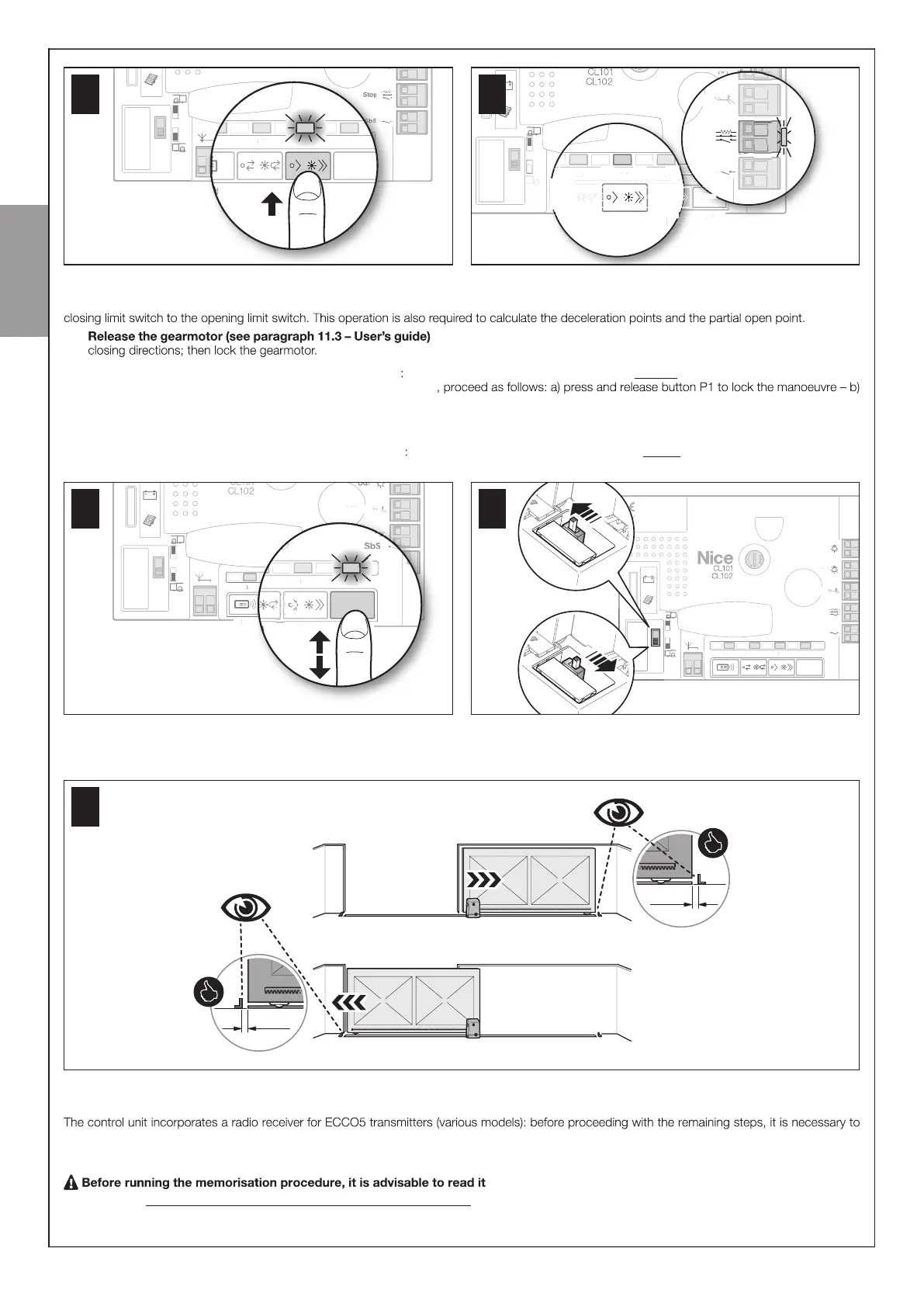
5.4 - MEMORISATION OF THE GATE LEAF LENGTH (opening and closing)
After recognition of the devices (Par. 5.3) it is necessary to make the control unit memorise the length of the gate leaf, which is measured from the
01. and move the gate to mid-travel so that it is free to move in both the opening and
02. On the control unit (Fig. 18 ) press and release button P1 wait for the control unit to execute the gate opening manoeuvre up to the opening limit
switch. Only if the manoeuvre is NOT an opening movement
shut o power to the control unit – c) invert the position of the selector on the control unit (Fig. 19) – d) restore power to the control unit – e) repeat
the learning procedure for the connected devices described in Paragraph 5.3 - MEMORISATION OF CONNECTED DEVICES - f) press and release
the P1 key.
03. On the control unit (Fig. 19 ) press and release button P1 wait for the control unit to execute the gate closing manoeuvre up to the closing limit
switch.
ECSbus
Aerial
Fuse 15A
P4
L4 L3 L2
P2
Sb S
L1
P1
E
bu
eri a
use 1
4
18
Fuse 1.6A T
Flash
ECSbus
Stop
Aerial
Sb S
OGI
Fuse 15A
L4 L3 L2
Sb S
L1
use 1.
las
E
bu
top
erial
b
Fuse 1
4
2
bS
1
19
04. Lastly, perform various opening and closing manoeuvres while checking that the gate leaf stops at least 2/3 cm from the mechanical stops during
both the opening and closing phases (Fig. 20 ). If this distance does not match the proper distance, modify the position of the limit switches.
20
5.5 - MEMORISATION OF THE 1
st
TRANSMITTER
memorise the 1
st
transmitter in Mode 1 – see procedure below.
To memorise additional transmitters, see Par. 9.3.
and observe the indicated times.
This procedure allows for simultaneously memorising all the transmitter keys , by automatically pairing them to the commands shown in Table 1 below.
A transmitter memorised in Mode 1 can control only a single automation.