English – 8
English
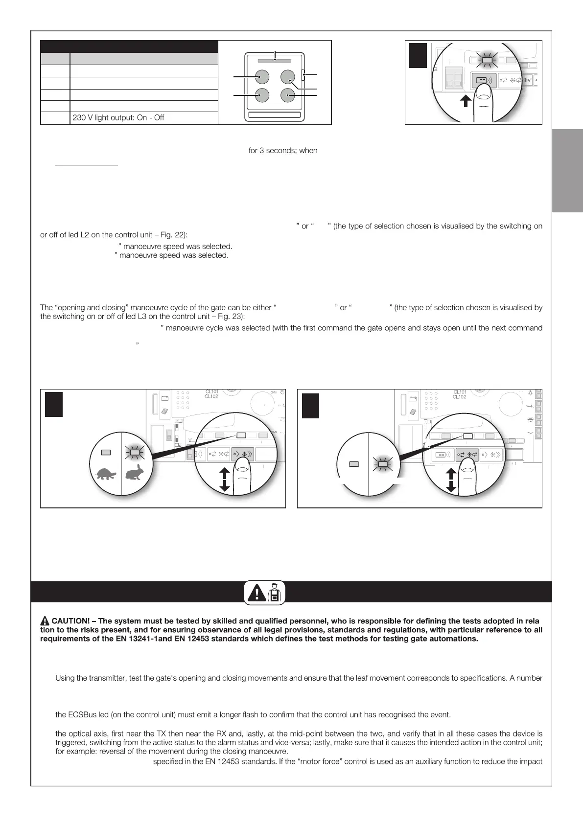
TABLE 1
T5
T2
T4
Fuse 1.6A T
Flash
ECSbus
Stop
Aerial
P4
L4 L3
P3
Keys Paired command
T1 Step-by-Step (SbS)
T2 Partial open
T3 Open only
T4 Close only
T5
Memorisation procedure
01. On the control unit (Fig. 21 ) press and hold button P4 led L4 switches on, release the button.
02. Within 10 seconds from releasing it, press and hold for 3 seconds any button of the transmitter to be memorised.
If the memorisation procedure is successful, led L4 (on the control unit) will ash 3 times.
03. To memorise o ther transmitters, repeat step 02 within the next 10 seconds otherwise the memorisation phase will terminate automatically.
5.6 - BASIC ADJUSTMENTS
5.6.1 - Choosing the gate manoeuvre speed
The opening and closing manoeuvre speed of the gate can be either “ slow fast
Led L2 o = the “ slow
Led L2 on = the “ fast
Procedure for selecting the desired speed
01. Press and release button P2 to invert the operating mode from slow to fast and vice-versa (Fig. 22 ).
5.6.2 - Choosing the gate manoeuvre operating cycle
semi-automatic automatic
Led L3 o = the “ semi-automatic
that causes it to close).
Led L3 lit = the “ automatic manoeuvre cycle was selected (with a single command the gate opens and re-closes automatically after a set time – to
adjust the pause time see Par. 9.1.1).
Procedure for selecting the desired cycle
01. Press and release button P3 to invert the operating mode from semi-automatic to automatic and vice-versa (Fig. 23 ).
ECSbus
Stop
Aerial
Fuse 15A
P4
L4 L3 L2
P3 P2
Sb S
L1
P1
E
bu
use 1
to
Sb
P4
L4 L3 L2
P3 P2
Sb S
L1
P1
22
ECSbus
Stop
Aerial
Sb S
OGI
Fuse 15A
P4
L4 L3 L2
P3 P2
Sb S
L1
P1
E
bu
to
b
Fuse 1
23
semi-automatic
automatic
21
6
TESTING AND COMMISSIONING
-
6.1 - TESTING
01. Ensure that all the instructions and warnings indicated in Chapter 1 have been strictly observed.
02.
of tests should be performed to ensure that the gate moves smoothly and that there are no assembly defects, incorrect settings, or any points of
friction.
03. Check the operation of all the system’s safety devices one-by-one (photocells, sensitive edges, etc.) In particular, whenever a device is activated
04. To check the photocells and make sure that there is no interference with other devices, pass a cylinder with 5 cm diameter and 30 cm length on
05. Measure the impact force as
force, test and identify the setting that obtains the best results.