English – 14
English
9.8 - CONNECTING THE 230 V LIGHT OUTPUT*
230 V, 500 W max
32
To perform the connection see Fig. 32 and consult the relevant instruction
manual.
* Not present in
FILO400SP/AU01 - FILO400ST/AU01 - FILO600SP/AU01 - FILO600ST/AU01
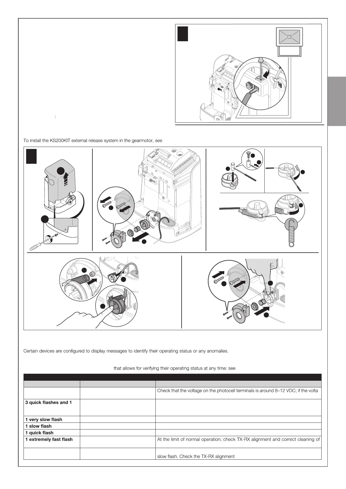
9.9 - INSTALLING THE EXTERNAL RELEASE SYSTEM model KS200KIT
Fig. 33 and consult the relevant instruction manual.
1
2
3
4
5
1
2
2
3
1
2
3
1
2
1
01.
04.
02. 03.
05.
33
9.10 - DIAGNOSTICS AND DEVICE SIGNALS
9.10.1 - Photocell signals
The photocells contain a SAFE led (Fig. 6/A ) Table 7.
TABLE 7
SAFE led (Fig. 6/A) Status Action
O The photocell is not powered or is
faulty
-
ge is correct, the photocell is probably faulty
second pause
Device not recognised by the control
unit
Repeat the recognition procedure on the control unit. Check that all pairs of pho -
tocells on the ECSBus have dierent addresses (consult the instruction manual of
the photocells)
The RX receives an excellent signal Normal operation
The RX receives a good signal Normal operation
The RX receives a poor signal Normal operation but check TX-RX alignment and correct cleaning of photocell lenses
The RX receives a bad signal
photocell lenses
Always lit The RX does not receive any signal Check for any obstruction between TX and RX. Check that the Led on TX emits a