English – 6
English
5
PROGRAMMING
Step D
5.1 - CONTROL UNIT KEYS
and (Fig. 12 )
P1 = Step-by-Step command
P2 = slow/fast movement speed selection (Par. 5.6.1)
P3 = semi-automatic/automatic operating cycle selection (Par.
5.6.2)
P4 = radio transmitter memorisation
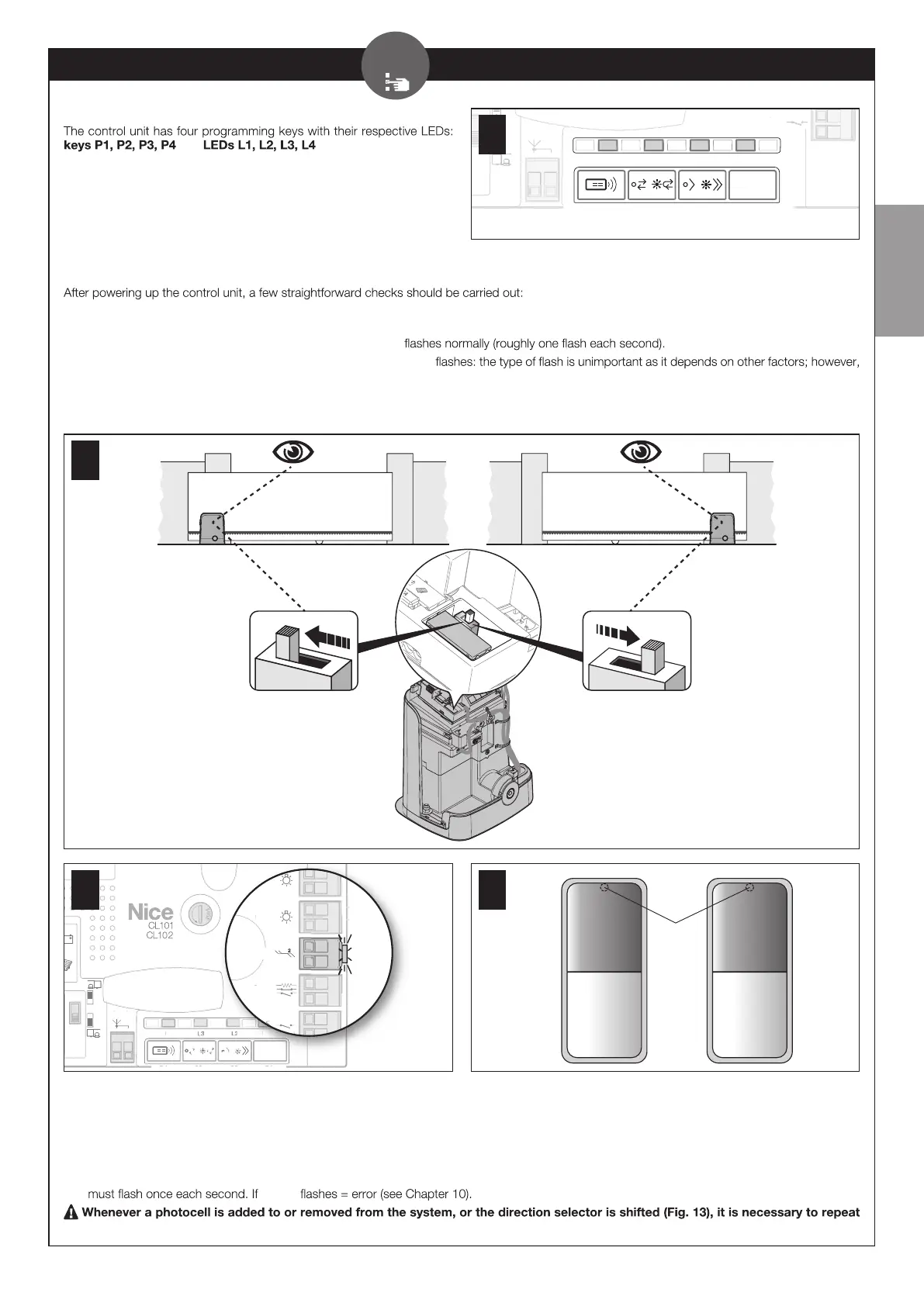
5.2 - PRELIMINARY CHECKS
01. Depending on the gearmotor’s installation position ( to the right or left of the gate), shift the selector as shown in Fig. 13 to determine the gate’s
opening direction.
02. Check on the control unit (Fig. 14 ) that the ECSBus led
02. On the Tx and Rx photocells (Fig. 15 ) check that the SAFE led
it is important that the led is not always o or always lit.
03. If all these checks are non-conforming, disconnect the power supply to the control unit and check the relevant connections of the cables. Other
useful information is contained in Chapters 9.9 and 10.
13
Fuse 1.6A T
Flash
ECSbus
Stop
Aerial
Sb S
OGI
L4
Sb S
L1
eri a
4
b
14
led
SAFE
TX RX
15
5.3 - MEMORISATION OF CONNECTED DEVICES
On completion of the preliminary checks (Par. 5.2), the control unit must be made to recognise the devices connected on the ECSBus and Stop
terminals.
01. On the control unit (Fig. 16 ) press and hold button P2 for at least 3 seconds then release it.
02. Wait a few seconds for the control unit to complete the device learning phase.
03. On the control unit (Fig. 17 ), at the end of the recognition procedure, the Stop led must remain lit and led L2 must turn o. The ECSBus led
led L2
the learning procedure for the connected devices.
Aerial
Sb S
P4
L4 L3 L2
P3 P2
Sb S
L1
P1
er
a
b
12