English – 5
English
At this point it is possible to install the accessories that belong to the system: for photocells PH200 > Par. 3.6 (Fig. 6) - for ashing light FL200
> Par. 3.7 (Fig. 7). For other optional accessories, consult the respective instruction manuals.
3.6 - INSTALLING THE PHOTOCELLS model PH200 (Fig. 6a - 6b)
The photocells can be mounted on the wall as described below (g. 6a), or inside the gearmotor (g. 6b); for this type of installation,
consult the instruction manual of the photocells.
• position each photocell 40/60 cm above the ground • position them on the opposite sides of the zone to be protected • position
them as close as possible to the gate (maximum distance = 15 cm) • a tube for passing the cables must be present in the fastening point
• orient the TX transmitter towards the central zone of the RX receiver (allowed misalignment: maximum 5°)
For the installation procedure see Fig. 6a - 6b.
3.7 - INSTALLING THE FLASHING LIGHT model FL200 (Fig. 7)
• The ashing light must be positioned near the gate in a clearly visible position. It can be fasted to a horizontal or vertical surface.
• For connection to the Flash terminal, no polarity needs to be observed; instead for connection of the shielded aerial cable, it is necessary to connect
the cable and sheath as shown in Fig. 8.
Choose the most suitable position in which to install the ashing light: it must be positioned near the gate in a clearly visible position. It can be fasted
to a horizontal or vertical surface.
For the installation procedure see Fig. 7.
PH200
FL200
4
ELECTRICAL CONNECTIONS
Step C
4.1 - ELECTRICAL CONNECTION TO THE CONTROL UNIT (Fig. 8)
01. Perforate the rubber membrane and insert the cables necessary to connect the various devices (Phase 01 - Fig. 8): leave the cables at least
40–50 cm long and secure them with cable ties (Phase 02 - Fig. 8).
02. Connect the various devices of the kit and any other components designed for being used on the system (optional and not included in the pack-
age) (Phase 03 - Fig. 8): It is not necessary to observe any polarity, with the exception of the shielded aerial cable which must be connected with
the cable and sheath as shown in Phase 03 - Fig. 8
4.2 - POWER SUPPLY CONNECTION
CAUTION! – The nal connection of the system to the mains power or replacement of the cable supplied MUST be performed exclu-
sively by a qualied and electrician, in compliance with local safety standards and the following instructions.
• For operational and programming tests of the automation, use the cable supplied, inserting the plug into an electrical socket. If the socket is a
long way from the automation, an extension may be used in this phase.
• For the testing and commissioning phase of the automation, it is necessary to connect the control unit permanently to the mains power supply,
by replacing the supplied cable. To connect the cable to the gearmotor’s control unit, proceed as described below:
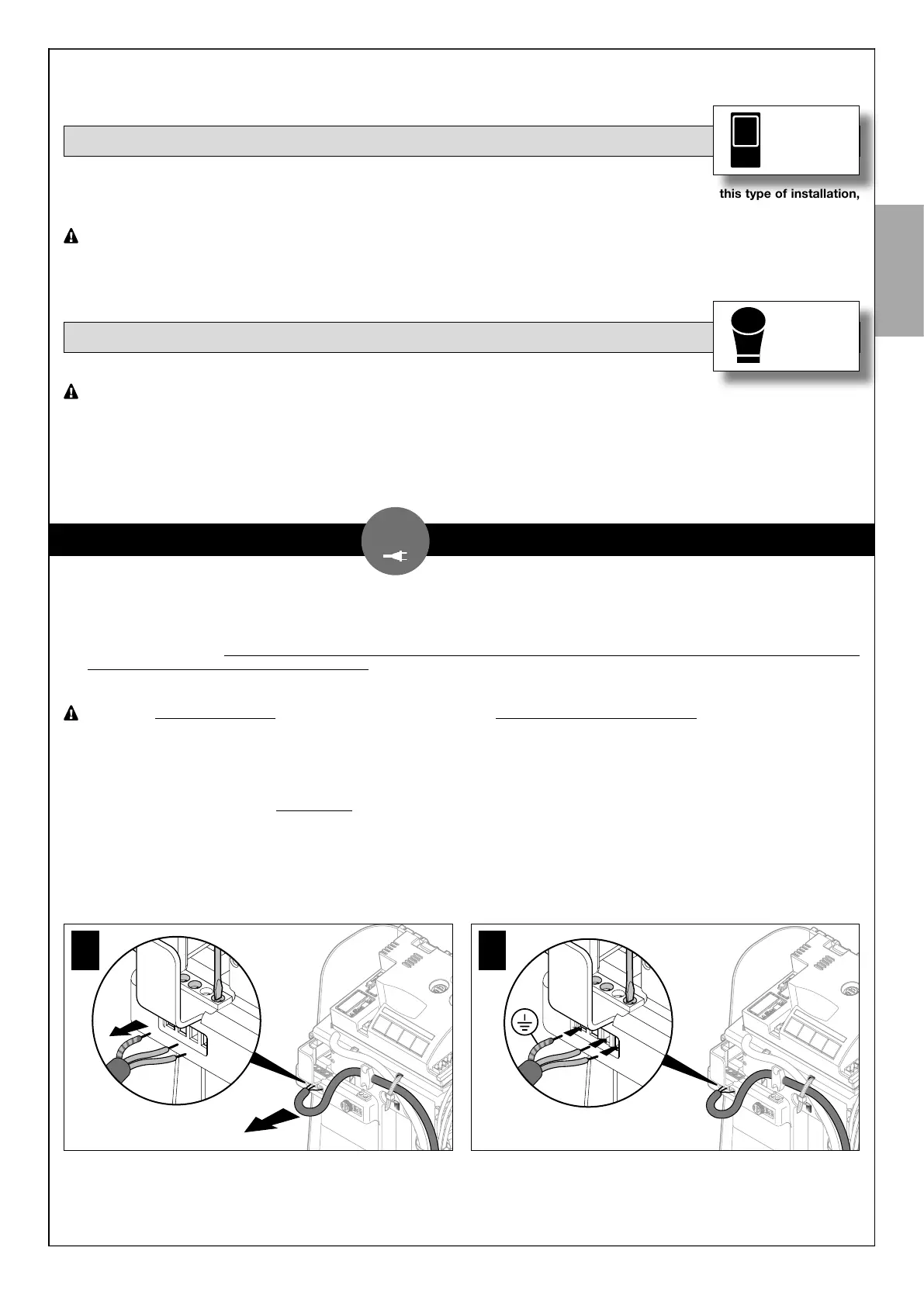
01. Make sure that the gearmotor plug is not plugged into the wall socket.
02. Disconnect the power cable from the gearmotor’s power supply terminal (Fig.10).
03. Loosen the collar and remove the power cable: replace it with the permanent power cable.
04. Connect the power cable to the gearmotor’s power supply terminal (Fig. 11).
05. Tighten the collar to secure the electric cable.
06. Before closing the gearmotor’s cover (Fig. 9) it is possible to programme the control unit (see Chapter 5).
10
11