ENGLISH – 13
4.2 WIRING DIAGRAM AND DESCRIPTION OF CONNECTIONS
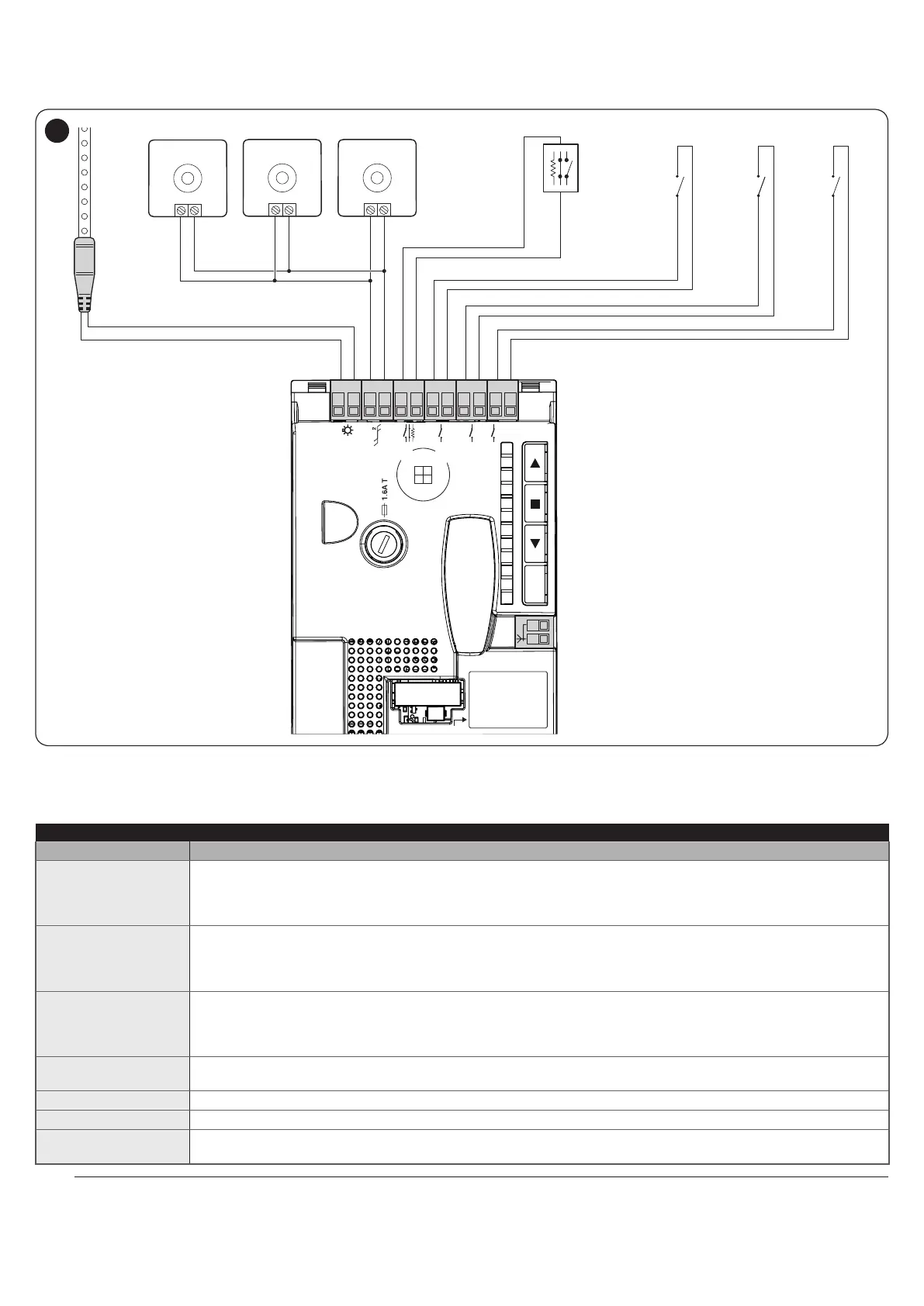
4.2.1 Wiring diagram
NO
NC
8K2
NO
NO
NO NO
TX
Bluebus
Bluebus
RX
Bluebus
MOTB/MOFB
L1L2L3L4L5L6L7L8
Flash
Bluebus
Stop
Sbs
Open
Close
Flash
Bluebus
Stop Sbs Open Close
Aerial
IBT4N
28
4.2.2 Description of connections
Table 3
ELECTRICAL CONNECTIONS
Terminals Description
FLASH
Output for warning light; it is possible to connect 12 V max 21 W lamps or a Nice LUCY B, MLB or MLBT
warning light.
It can also be programmed for other functions (refer to the “PROGRAMMING” chapter) or recongured
through the Oview programmer.
BLUEBUS
This terminal can be used to connect compatible devices, which are all connected in parallel with only two
wires carrying both the electric power and communication signals.
For further information on the BlueBUS, refer to the “Addressing of devices connected with the BlueBUS
system” paragraph.
STOP
Input for devices that suspend or even stop the current manoeuvre; “Normally Closed” and “Normally Open”
contacts or xed resistor devices can be connected by suitably conguring the input.
For further information on the STOP function, refer to the “Modifying the STOP input conguration”
paragraph.
SbS
Input for devices that control the movement in Step-by-Step mode; it is possible to connect “Normally Open”
contacts.
OPEN
Input for devices that control the opening movement only; it is possible to connect “Normally Open” contacts.
CLOSE
Input for devices that control the closing movement only; it is possible to connect “Normally Open” contacts.
ANTENNA
input for connecting the radio receiver antenna; the antenna is incorporated in Nice LUCY B, MLB and MLBT
warning lights.
a
If the programming of the outputs is modied, check that the connected device matches the type of voltage
chosen.