16 – ENGLISH
5.5 CONNECTING OTHER DEVICES
If the user needs to power external devices, such as a radio
receiver or the light of the key selector switch, power can be
tapped as shown in the gure.
The power supply voltage is 24Vc -30% ÷ +50% with a maxi-
mum available current of 100mA.
STOP
SBS
(+)(-)
33
TESTING AND COMMISSIONING
6
6 TESTING AND COMMISSIONING
These are the most important phases of the automation’s con-
struction, as they ensure maximum safety of the system. The
test can also be used to periodically verify the devices making
up the automation.
m
Testing and commissioning of the automation must
be performed by skilled and qualied personnel,
who are responsible for the tests required to ver-
ify the solutions adopted according to the risks
present, and for ensuring that all legal provisions,
standards and regulations are met, in particular all
the requirements of the EN 12445 standard, which
denes the test methods for checking gate automa-
tions.
The additional devices must undergo specic testing, both in
terms of their functions and their proper interaction with the con-
trol unit. Refer to the instruction manuals of the individual devic-
es.
6.1 TESTING
To run the test:
1. verify that all the instructions stated in the “GENERAL
SAFETY WARNINGS AND PRECAUTIONS” chapter
have been strictly observed
2. check that the boom is correctly balanced (see paragraph
“Boom balancing“)
3. check that the manual unlocking device works properly
(see paragraph “Manually unlocking and locking the
gearmotor“)
4. using the control devices (transmitter, control push-but-
ton, key selector, etc.), test the boom opening, closing
and stopping phases, ensuring that the movement match-
es the specications. Several tests should be conducted
to assess the boom’s movement and to check for any as-
sembly or adjustment defects or any particular points of
friction
5. check, one-by-one, that all safety devices mounted on the
system (photocells, sensitive edges, etc.) work properly.
Each time a device intervenes, the “Bluebus” LED on the
control unit will emit two faster ashes to conrm the rec-
ognition
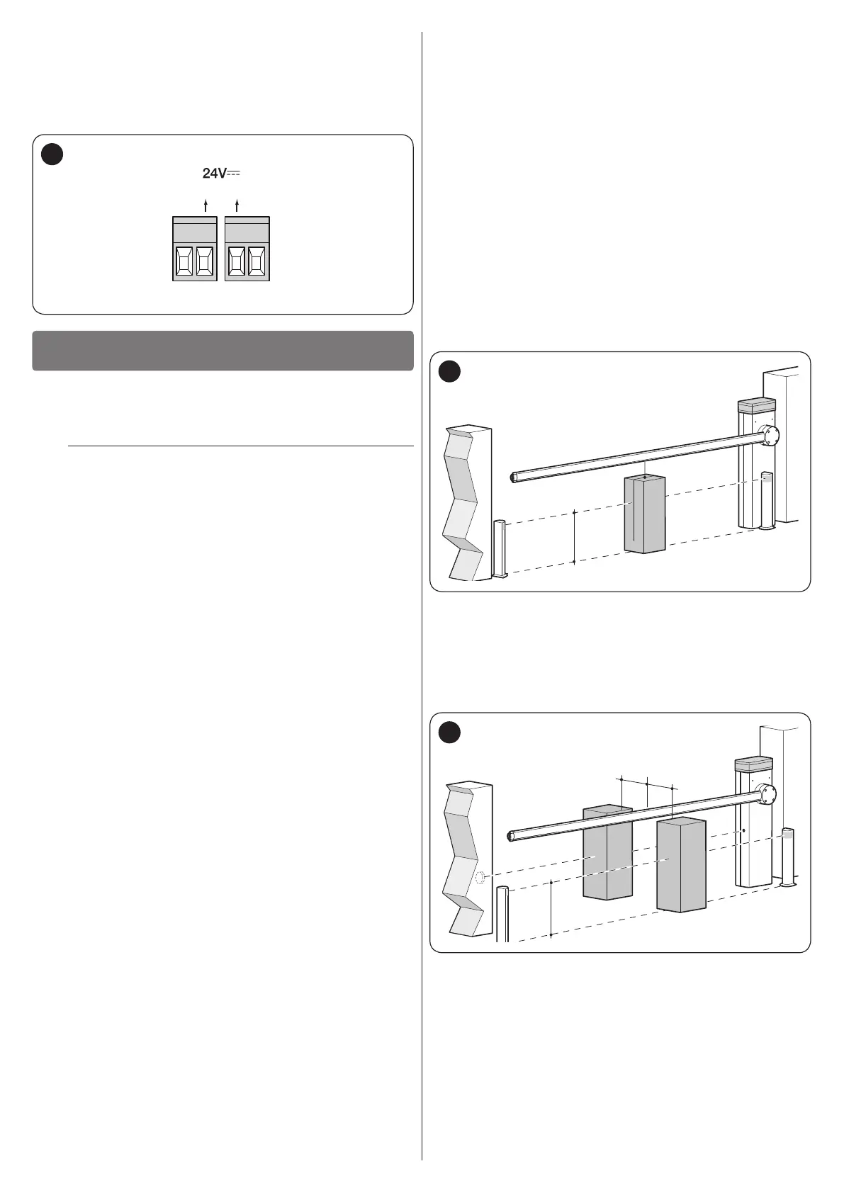
6. verify the correct operation of the photocells in the follow-
ing way:
– depending on whether one or two pairs of photocells
have been installed, one or two blocks of rigid ma-
terial (e.g. wooden panels) are required, measuring
70x30x20 cm. Each block must have three sides of re-
ective material (e.g. mirror or glossy white paint), one
for each dimension, and three sides of opaque material
(e.g. matt black paint). To test the photocells positioned
50 cm above the ground, the block must be placed on
the ground, or raised to 50 cm when testing photocells
positioned 1 m above the ground
– if the test is on a pair of photocells, the testing block
must be placed directly under the centre of the boom
with the 20 cm sides facing the photocells and moved
along the entire length of the boom
300
200
700
500
34
– if the test is on two pairs of photocells, the test must
rst be performed individually for each pair of photo-
cells using one testing block and then repeated using
two testing blocks; each testing block must be posi-
tioned laterally in relation to the centre of the boom, at
a distance of 15 cm and then moved along the entire
length of the boom
300
200
700
300
200
700
500
150
150
35