14 – ENGLISH
4.3 ADDRESSING OF DEVICES CONNECTED
WITH THE BLUEBUS SYSTEM
By means of addressing using special jumpers, the “BlueBUS”
system enables the user to make the control unit recognise the
photocells and assign the correct detection function.
The addressing operation must be done on both the TX and RX
photocells (setting the jumpers in the same way), while making
sure there are no other pairs of photocells with the same ad-
dress.
A photocell addressing diagram is shown below, based on the
type of photocell.
FOTO 2
FOTO II
FOTO 2 II
FOTO 1
FOTO II
FOTO
29
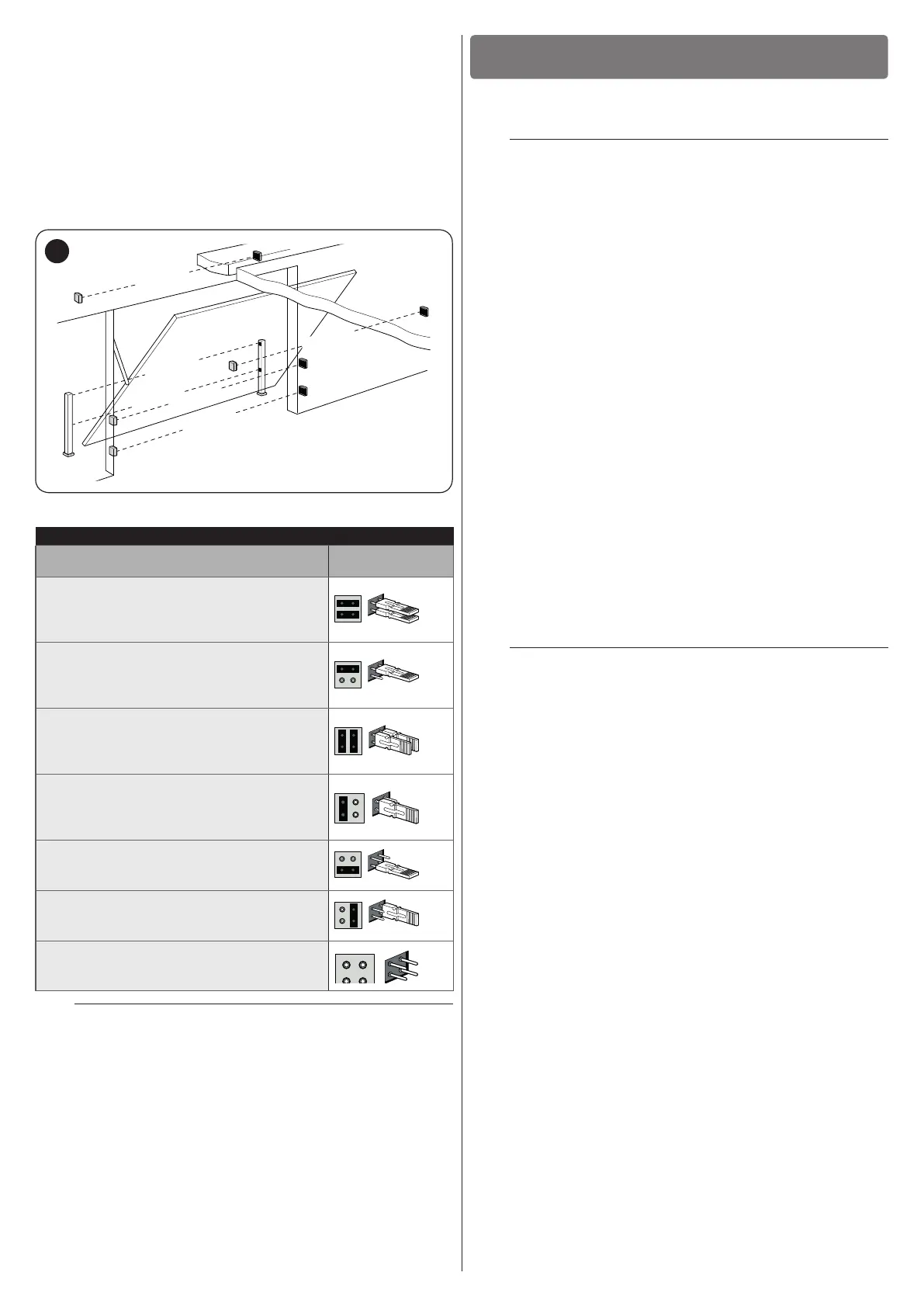
Table 4
PHOTOCELL ADDRESSES
Photocell
Position of the
jumpers
FOTO (PHOTO)
External photocell h = 50 activated during
the closing phase (stops and reverses the
gate’s movement)
FOTO II (PHOTO II)
External photocell h = 100 activated
during the closing phase (stops and
reverses the gate’s movement)
FOTO 1 (PHOTO 1)
Internal photocell h = 50 activated during
the closing phase (stops and reverses the
gate’s movement)
FOTO 1 II (PHOTO 1 II)
Internal photocell h = 100 activated during
the closing phase (stops and reverses the
gate’s movement)
FOTO 2 (PHOTO 2)
External photocell activated during the
opening phase
FOTO 2 II (PHOTO 2 II)
Internal photocell activated during the
opening phase
FOTO 3 (PHOTO 3)
Single photocell covering the entire
automation
m
At the end of the installation procedure, or after
photocells or other devices have been removed,
it is necessary to complete the learning procedure
(see the “Device learning” paragraph).
FINAL CHECKS AND START-UP
5
5 FINAL CHECKS AND START-UP
5.1 POWER SUPPLY CONNECTION
a
The power supply connections must only be made
by qualied and experienced personnel possessing
the necessary requirements and in full conformity
to the laws, regulations and standards in force.
Connect the control unit to a power line equipped with a safety
earthing system. Install a circuit breaker with a contact gap that
ensures full disconnection in the Category III overvoltage condi-
tions, or mount a plug and socket system.
As soon as the product is powered, a few simple checks should
be carried out:
1. check that the display switches on.
2. make sure that the LEDs on the photocells (both the TX
and RX) also ash; the type of ashing is irrelevant, since
it depends on other factors.
3. check that the device connected to the FLASH output or
the LED warning light XBA7 is switched off (with factory
setting).
If the above conditions are not satised, immediately switch
off the power supply to the control unit and carefully check the
electrical connections.
Further useful information on searching and diagnosing faults is
included in the “Troubleshooting” paragraph.
5.2 DEVICE LEARNING
Once the power supply has been connected, the control unit
must recognise the devices connected to the “BlueBUS” and
“STOP” inputs. Prior to this phase, LEDs “L1” and “L2” will ash
to signal that the device learning procedure must be performed.
m
The learning phase must be carried out even if no
device is connected to the control unit.