24 – ENGLISH
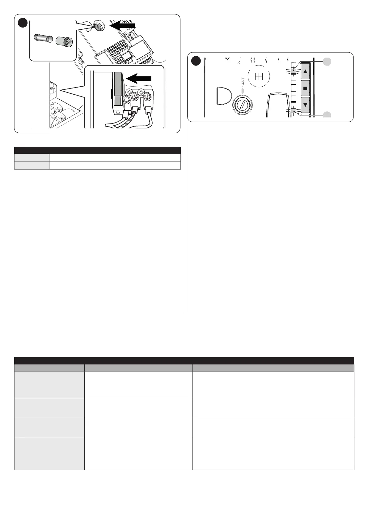
F1
F2
42
Table 9
CHARACTERISTICS OF FUSE F1
F1
Mains power supply fuse = 1.0 A delayed
F2
Control unit fuse = 1.6 A delayed
8.2 ANOMALY LOG
The gearmotor allows for displaying any anomalies that oc-
curred in the last 8 manoeuvres, for example, the interruption of
a manoeuvre due to the intervention of a photocell or sensitive
edge.
L1L2L3L4L5L6L7L8
Flash
Bluebus
Stop
Sbs
Open
Close
L1
43
To do this:
1. press and hold the
o
button until LED “L1” starts ashing
2. release the
o
button when LED “L1” starts ashing
3. press the
p
or
q
button to shift the ashing LED to “L8”,
that is, the “entry LED” for the “List of anomalies” param-
eter
4. press and hold the
o
button. With the
o
button pressed:
– wait roughly 3 seconds, after which the LEDs corre-
sponding to the manoeuvres that had anomalies will
light up. LED L1 indicates the result of the most recent
manoeuvre, while LED L8 indicates the result of the
eighth manoeuvre. If the LED is lit, it means that anom-
alies occurred during the manoeuvre; if the LED is off,
the manoeuvre terminated without any anomalies
– press the
p
or
q
button to select the desired manoeu-
vre: the corresponding LED will ash the same number
of times as those emitted by the warning light following
an anomaly (see “Table 10”)
5. release the
o
button.
8.3 SIGNALLING THROUGH WARNING LIGHT
If a warning light (or a LED warning light is used – optional accessory) is connected to the control unit’s FLASH output, it will ash
once a second during manoeuvres. If any anomalies occur, the warning light will emit shorter ashes which are repeated twice with
a 1-second pause between each pair. The same signals are also emitted by the LED warning light (optional accessory).
Table 10
FLASH WARNING LIGHT SIGNALS
Fast ashes Cause ACTION
2 ashes
1-second pause
2 ashes
Intervention of a photocell
At the start of the manoeuvre, one or more photocells
are blocking the movement; check whether there are any
obstacles. During the manoeuvre, this is normal if an obstacle
is present.
3 ashes
1-second pause
3 ashes
Intervention of the “Motor Force” limiter
During the gate’s movement, the motors encountered more
resistance; verify the cause and increase the motor force if
necessary.
4 ashes
1-second pause
4 ashes
Intervention of the STOP input
At the start of the manoeuvre or during the movement, the
STOP input intervened; identify the cause.
5 ashes
1-second pause
5 ashes
Error in the internal parameters of the
control unit
Disconnect and reconnect the power supply. If the error
persists, delete the entire memory (refer to the “Memory
deletion” paragraph) and redo the installation. If the condition
persists, there may be a serious fault or the electronic circuit
board needs to be replaced.