ENGLISH – 17
– during these tests, the testing block must be detected
by the photocells in any position it lies along the entire
length of the boom
7. check that there are no interferences between the photo-
cells and other devices:
– block the line of sight between the pair of photocells
with a cylinder (diameter 5 cm, length 30 cm), by mov-
ing it close to the TX photocell rst then next to the RX
photocell and then at the mid-point between the two
36
– check that the device intervenes in all cases, switching
from the active to the alarm status and vice-versa
– check that it triggers the intended action in the control
unit (e.g. a reversal of the movement during the closing
manoeuvre)
8. check on the safeguard against the lifting hazard: in
automations with vertical movement it is necessary to ver-
ify that there is no lifting hazard. This test can be carried
out in the following way:
– hang a 20 kg load (e.g. a sand bag) midway along the
boom’s length
– send an opening command and check that during the
manoeuvre the boom does not exceed a height of 50
cm above its closed position
– if the boom exceeds this height, the motor force must
be reduced (refer to the chapter “PROGRAMMING“)
9. if potentially dangerous situations due to the boom’s
movement have been prevented by limiting the impact
force, the latter must be measured according to the EN
12445 standard and, if the “motor force” control is used
to aid the system in reducing the impact force, it is neces-
sary to test various adjustments to nd the one that gives
the best results
10. checking the efciency of the unlocking system:
– put the boom in the closed position and manually un-
lock it (see paragraph “Manually unlocking and lock-
ing the gearmotor“)
– verify that this occurs smoothly
– verify that the manual force to move the boom during
the opening phase does not exceed 200 N (roughly 20
kg)
– the force is measured perpendicularly to the boom at 1
m from the rotation axis
11. verication of the power supply disconnection sys-
tem: operate the power disconnection device and dis-
connect any available back-up batteries; check that all
the LEDs on the control unit are OFF and that the boom
remains stationary when a command is sent. Check the
efciency of the locking system to prevent any uninten-
tional or unauthorised connection.
6.2 COMMISSIONING
a
Commissioning can only be performed after all test-
ing phases have been successfully completed.
a
Before commissioning the automation, ensure that
the owner is properly informed of all residual risks
and hazards.
a
The gate cannot be commissioned partially or un-
der “temporary” conditions.
To commission the automation:
1. compile the automation’s technical le, which must in-
clude the following documents: overall drawing of the
automation, wiring diagram, risk assessment and relative
solutions adopted, the manufacturer’s declaration of con-
formity for all devices used and the declaration of con-
formity compiled by the installer
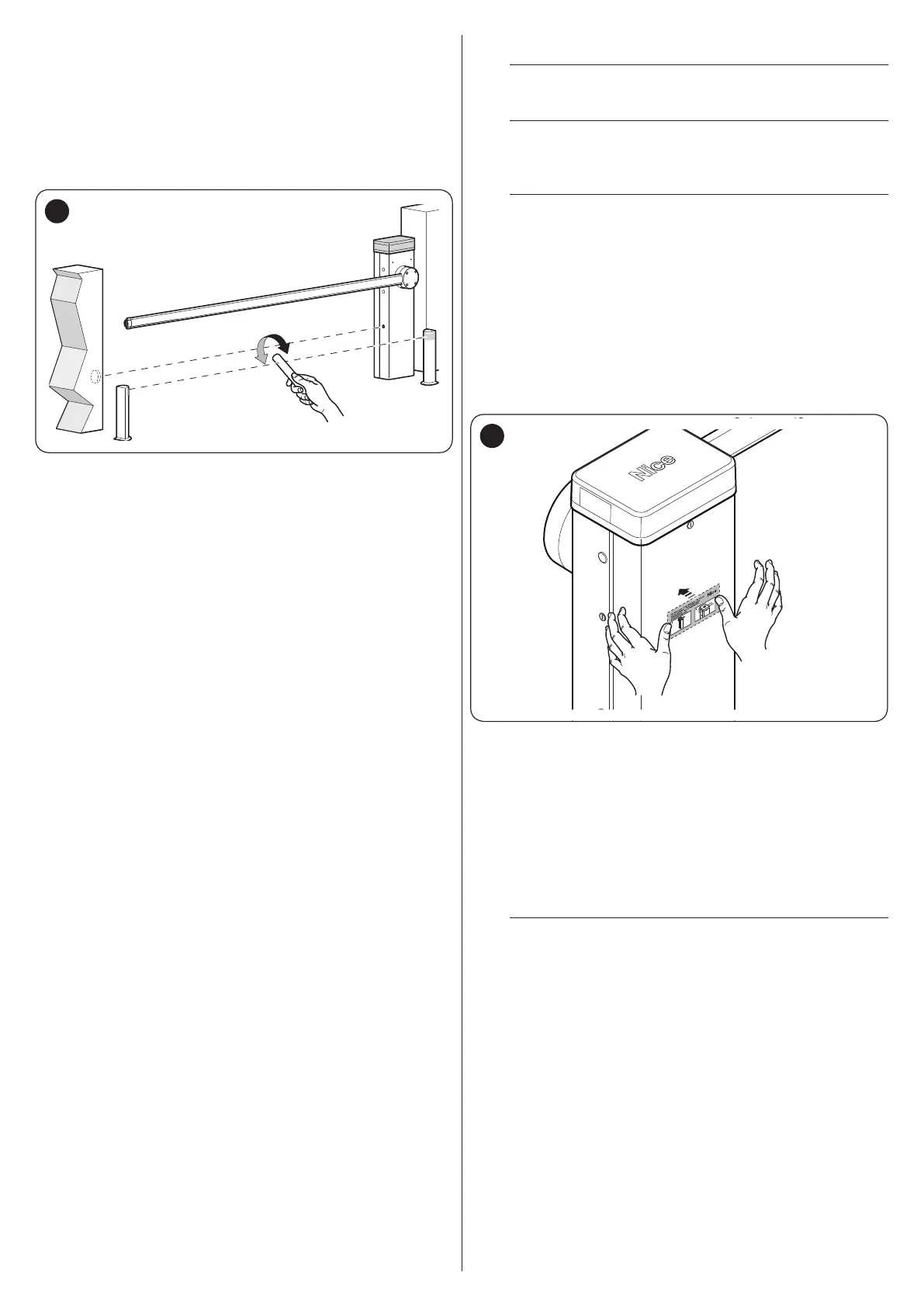
2. afx a permanent label or sign on the cubicle specifying
the operations for unlocking the gate and manoeuvring it
manually “Figure 37“
37
3. afx a data plate to the cubicle specifying at least the
following data: type of automation, name and address of
the manufacturer (responsible for commissioning), serial
number, year of manufacture and CE mark
4. compile the declaration of conformity of the automation
and hand it to the owner of the automation
5. compile the User Manual of the automation and hand it to
the owner of the automation
6. compile and provide the owner with the automation’s
“Maintenance schedule”, containing the maintenance in-
structions for all the automation’s devices.
l
For all the above-mentioned documentation, Nice –
through its technical assistance service – provides
the following: pre-completed forms.