ENGLISH – 21
LEVEL 2 FUNCTIONS (ADJUSTABLE PARAMETERS)
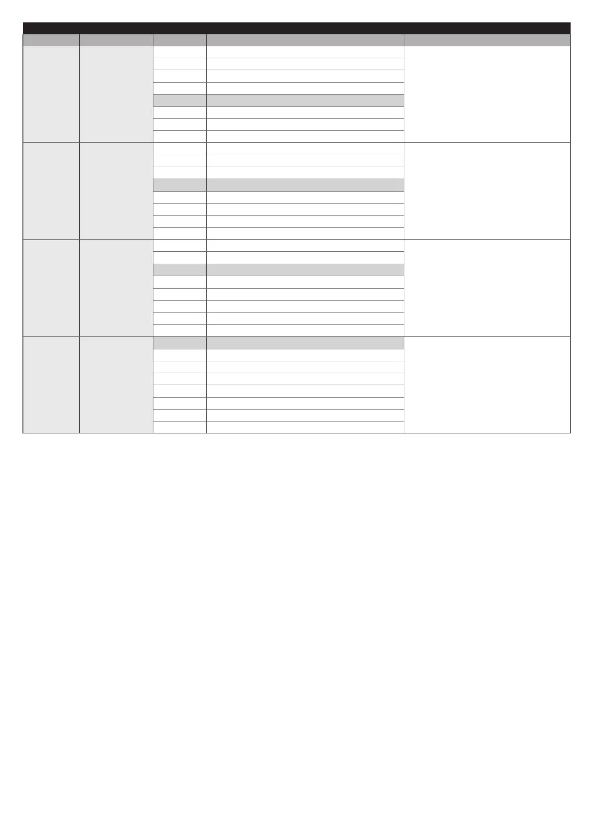
Entry LED Parameter LED (level) Set value Description
L5*
Motor force on
opening
L1 Force 1 (low)
Sets the system for controlling the motor
force, to adapt it to the weight of the
boom during the opening manoeuvre.
L2 Force 2
L3 Force 3
L4 Force 4
L5 Force 5
L6 Force 6
L7 Force 7
L8 Force 8 (high)
L6*
Motor force on
closing
L1 Force 1 (low)
Sets the system for controlling the motor
force, to adapt it to the weight of the
boom during the closing manoeuvre.
L2 Force 2
L3 Force 3
L4 Force 4
L5 Force 5
L6 Force 6
L7 Force 7
L8 Force 8 (high)
L7*
Maintenance
notice
L1 2500
Adjusts the number of manoeuvres
after which the automation maintenance
request is triggered (see the “
“Maintenance notice” function”
paragraph).
L2 5000
L3 10000
L4 15000
L5 20000
L6 30000
L7 40000
L8 50000
L8
List of
malfunctions
L1 Result of 1st manoeuvre (most recent)
Allows for viewing the type of anomalies
that occurred in the last 8 manoeuvres
(refer to the “Anomaly log” paragraph).
This is a read-only parameter, which
means that its values cannot be
modied.
L2 Result of 2nd manoeuvre
L3 Result of 3rd manoeuvre
L4 Result of 4th manoeuvre
L5 Result of 5th manoeuvre
L6 Result of 6th manoeuvre
L7 Result of 7th manoeuvre
L8 Result of 8th manoeuvre
All parameters can be adjusted as desired without any problems; only the “Motor force on opening” and “Motor force on closing”
settings require special attention:
– high force values should not be used to compensate for points of abnormal friction affecting the boom; excessive force can jeop-
ardise the operation of the safety system or damage the boom
– if the “Motor Force” control is used to aid the impact force reduction system, measure the force again after each adjustment in
accordance with the EN 12445 standard
– wear and weather conditions may affect the boom gate’s movement, therefore periodic force readjustments of the motor force
may be necessary.
(*) If the value of a parameter falls between two adjacent values, the control unit will switch on intermittently the two LEDs iden-
tifying the value itself. If necessary, the values can be rounded off by pressing the
p
or
q
button to round off respectively
to the lower or higher value among the two values highlighted by the control unit.
Example: Maintenance warning = 7000 manoeuvres - LEDs L2 and L3 will ash. Pressing the
q
button rounds off to value
L3 (10000), while pressing the
p
button rounds off to value L2 (2500).
If the value of a parameter is below the minimum value or above the maximum value among those listed in the table, the
control unit will switch on intermittently LED L1 or L8 respectively. If necessary, the values can be rounded off by pressing
the
p
or
q
button to round off to the nearest value.
Example: Pause Time = 3 seconds - LED L1 will ash. Pressing the
p
button rounds off to value L1 (10 s) and L1 will no
longer ash because the parameter will have been rounded off to a known value.
(**) If the conguration has not been learned, when LEVEL 2 of the MENU opens up, the control unit will propose the default
conguration.