Safety
information
Product
information
Mechanical
installation
Electrical
installation
Getting
started
Running the
motor
Drive
parameters
Communications Diagnostics Technical data
UL Listing
Information
Commander S100 User Guide 101
If the master request is valid, the slave will respond with the requested
information using the following format.
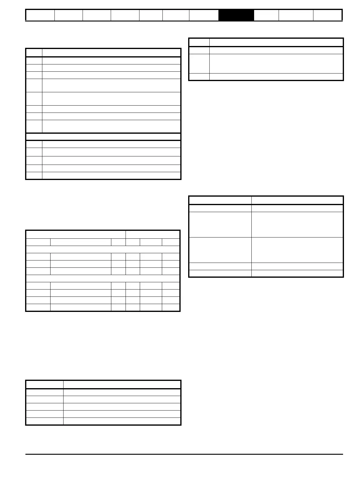
Table 8-11 Slave response
The Object ID, length and value are returned for each object in the list.
1
- The value of n is dependent on the number of the object in the list and
the previous object length, with the first object numbered 1.
The byte number, n (starting at 0) for each object is shown in the
following table.
Table 8-12 Returned object's attributes bytes
8.1.7 Exceptions
The slave will respond with an exception response if an error is detected
in the master request. If a message is corrupted and the frame is not
received or the CRC fails then the slave will not issue an exception. In
this case the master device will time out. If a write multiple (FC16 or
FC23) request exceeds the slave maximum buffer size then the slave
will discard the message. No exception will be transmitted in this case
and the master will time out.
Exception message format
The slave exception message has the following format.
Exception codes
The following exception codes are supported.
Parameter over range during block write FC16
The slave processes the write block in the order the data is received. If a
write fails due to an out of range value then the write block is terminated.
However, the slave does not raise an exception response, rather the
error condition is signalled to the master by the number of successful
writes field in the response.
Parameter over range during block read/write FC23
There will be no indication that there has been a value out of range
during a FC23 access.
8.1.8 CRC
The CRC is a 16bit cyclic redundancy check using the standard CRC-16
polynomial x16 + x15 + x2 + 1. The 16 bit CRC is appended to the
message and transmitted LSB first.
The CRC is calculated on ALL the bytes in the frame.
8.1.9 Device compatibility parameters
All devices have the following compatibility parameters defined:
Byte Description
0 Slave node address
1 Modbus Function Code (0x2B)
2 MEI Type (0x0E)
3 Read Device ID Code
(0x01): Basic identification (mandatory)
(0x02): Regular identification (optional)
4 Conformity level
(0x01): Basic identification (mandatory)
(0x02): Regular identification (optional)
5 More follows (0x00)
6 Next object ID (0x00)
7
Number of objects in
list
(0x03): Basic identification (mandatory)
(0x04): Regular identification (optional)
List of enumerated objects
n1 Object ID
n
1
+ 1
Object length (bytes)
n
1
+ 2
Object value start byte
66 CRC LSB
67 CRC MSB
Object Return Byte
Number Name ID ID Length Value
Basic identification (mandatory)
1 Vendor name 0x00 8 9 10
2 Product code 0x01 28 29 30
3 Major/minor revision 0x02 55 56 57
Regular identification (optional)
4 Vendor URL 0x03 8 9 10
5 Product name 0x04 31 32 33
6 Model name 0x05 42 43 44
7 Application name 0x06 48 49 50
Byte Description
0 Slave source node address
1 Original function code with bit 7 set
2 Exception code
3 CRC LSB
4 CRC MSB
Code Description
1 Function code not supported
2
Register address out of range, or request to read too many
registers. Can occur from FC 43 if the MODBUS
encapsulated interface ID is not supported.
4 Unrecoverable error
Parameter Description
Device ID Unique device identification code
Minimum slave response
time
The minimum delay between the end of a
message from the master and the time at
which the master is ready to receive a
response from the slave.
Maximum slave response
time
When global addressing, the master
must wait for this time before issuing a
new message. In a network of devices,
the slowest time must be used.
Maximum baud rate 115200 bps
Maximum buffer size Determines the maximum block size.