Safety information Introduction Product information System configuration
Mechanical
Installation
Electrical Installation
Unidrive M Modular Installation Guide 81
Issue Number: 2
N
Any signal cables which are carried inside the motor cable (i.e. motor
thermistor, motor brake) will pick up large pulse currents via the cable
capacitance. The shield of these signal cables must be connected to
ground close to the point of exit of the motor cable, to avoid this noise
current spreading through the control system.
N
The SAFE TORQUE OFF drive enable terminal is a positive logic input
only. It is not affected by the setting of Input Logic Polarity (08.029).
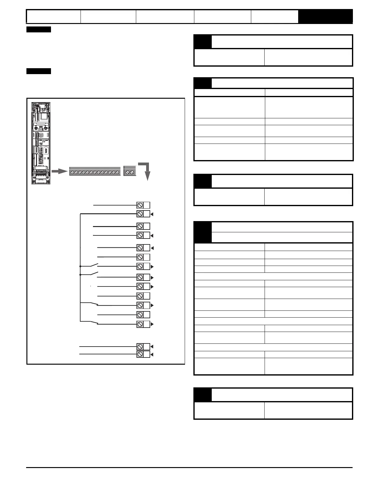
Figure 6-30 Default terminal functions
*The SAFE TORQUE OFF / Drive enable terminal is a positive logic input
only.
6.12.4 Unidrive M702 control terminal specification
1
41
42
0 V common
0 V common
1
2
3
4
5
6
7
8
9
10
11
41
42
Digital Output 1
Run forward
Run reverse
SAFE TORQUE OFF
Input 1*
Relay
(Over voltage
category II)
Drive OK
13
+24 V
0 V common
0 V common
12
13
0 V common
+24 V
SAFE TORQUE OFF
Input 2*
Digital Output 2
1 0 V common
Function
Common connection for all
external devices
2 +24 V user output (selectable)
Terminal 2 default function +24 V user output
Programmability
Can be switched on or off to act as a fourth
digital output (positive logic only) by setting
the source Pr 08.028 and source invert
Pr 08.018
Nominal output current 100 mA
Maximum output current
100 mA
200 mA (total including all Digital I/O)
Protection Current limit and trip
Sample / update period
2 ms when configured as an output (output
will only change at the update rate of the
source parameter if slower)
3 0 V common
Function
Common connection for all
external devices
4
Digital Output 1
5 Digital Output 2
Terminal 4 default function AT ZERO SPEED output
Terminal 5 default function
Type Positive logic voltage source outputs
Input / output mode controlled by... Pr 08.031, Pr 08.032
Operating as an input
Logic mode controlled by... Pr 08.029
Absolute maximum applied voltage
range
-3 V to +30 V
Impedance
>2 mA @15 V from IEC 61131-2, type 1,
6.6 k Ω
Input thresholds 10 V ±0.8 V from IEC 61131-2, type 1
Operating as an output
Nominal maximum output current 100 mA (DIO1 & 2 combined)
Maximum output current
100 mA
200 mA (total including all Digital I/O)
Common to all modes
Voltage range 0 V to +24 V
Sample / Update period 2 ms (output will only change at the update
rate of the source parameter
6 0 V common
Function
Common connection for all
external devices