Safety information Product information Mechanical installation Electrical installation Multi axis system design Technical data
Digitax HD M75X Series Installation and Technical Guide 49
Issue Number: 5
4.1.1 Ground connections
The drive must be connected to the system ground of the supply. The ground wiring must conform to local regulations and codes of practice.
For further information on ground cable sizes, refer to Table 4-1 below.
Table 4-1 Protective ground cable ratings
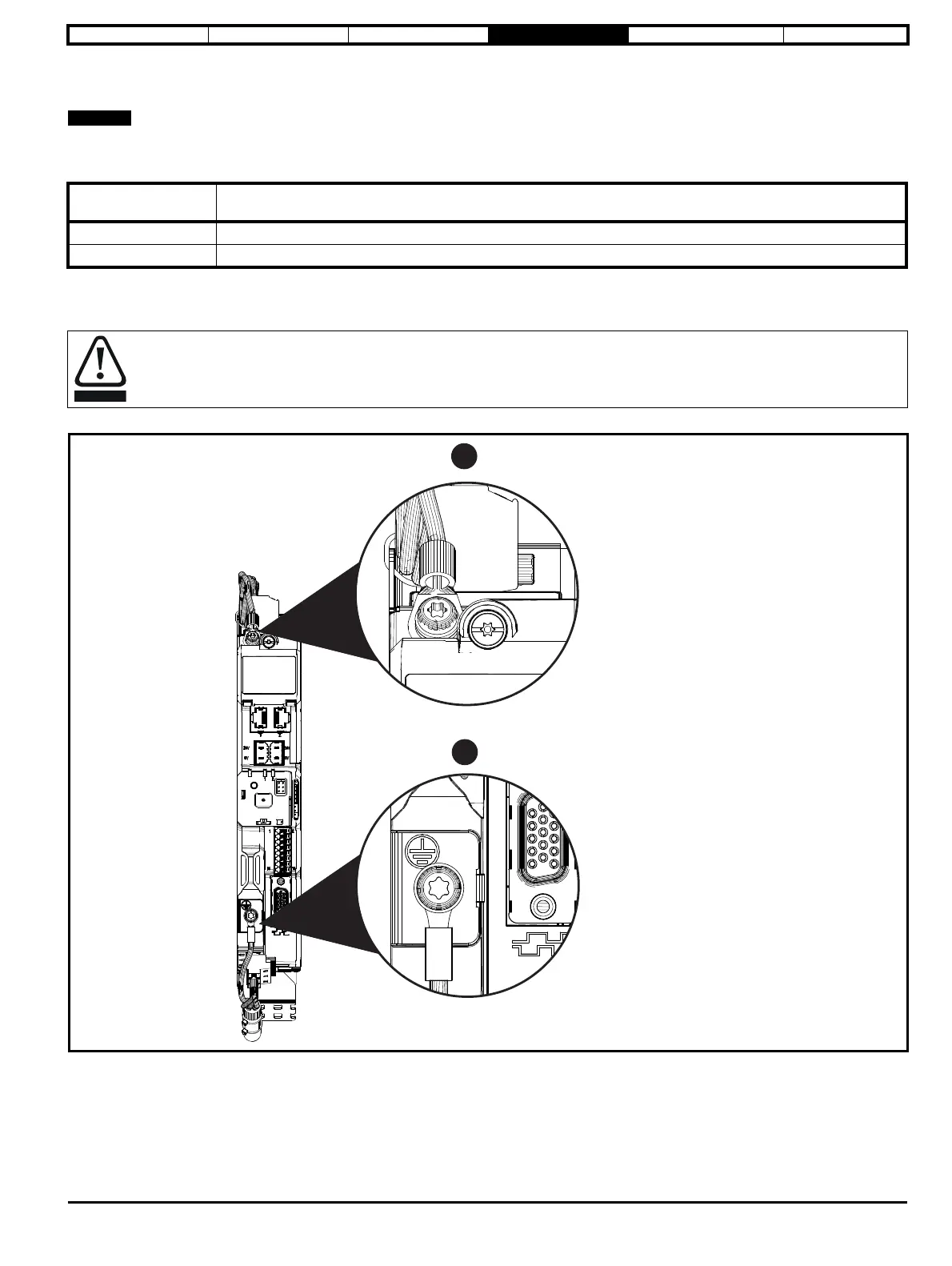
The supply and motor ground connections are made using the M4 threaded holes in the metal side plate of the drive. Connections are located at the
top and bottom of the drive. See Figure 4-2 for details.
Figure 4-2 Supply and motor ground connections
Input phase
conductor size
Minimum ground conductor size
≤ 10 mm
2
Either 10 mm
2
or two conductors of the same cross-sectional area as the input phase conductor
> 10 mm
2
and ≤ 16 mm
2
The same cross-sectional area as the input phase conductor
The ground loop impedance must conform to the requirements of local safety regulations.
The drive must be grounded by a connection capable of carrying the prospective fault current until the protective device (fuse, etc).
disconnects the AC supply.
The ground connections must be inspected and tested at appropriate intervals.
1. Supply ground connection.
2. Motor ground connection.