Safety information Product information Mechanical installation Electrical installation Multi axis system design Technical data
52 Digitax HD M75X Series Installation and Technical Guide
Issue Number: 5
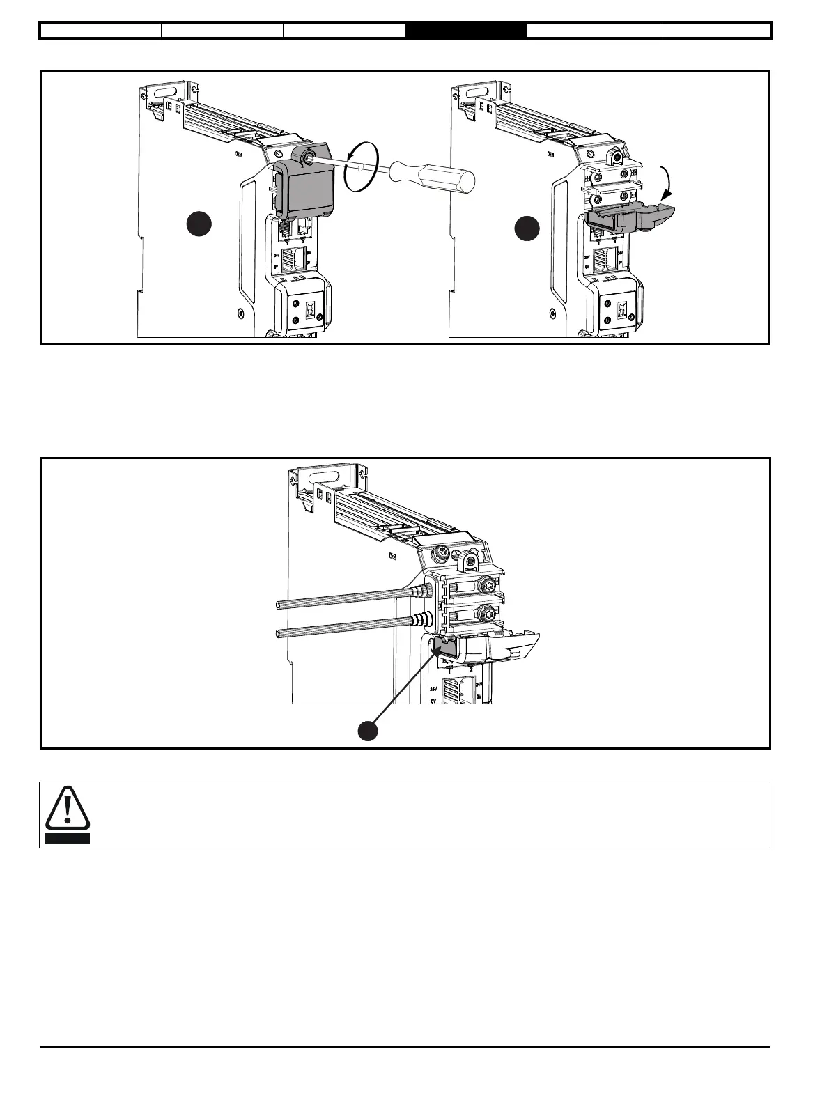
Figure 4-4 Opening of the DC terminal cover (frame 1, 2 and 3)
1. Undo the Torx slotted screw (T10 torx screwdriver).
2. The DC cover can then be hinged downwards or removed.
When replacing the terminal covers, the M3 screw should be tightened to a torque of 1 N m (8.9 lb in).
4.3.2 DC busbar cable connection
Cable connections to the DC terminals should be made with a suitably insulated M4 ring crimp (up to maximum 6 mm
2
cable).
Figure 4-5 DC supply connections and cable routing
• Remove only one DC terminal cover breakout tab (1) when supplying a standalone drive.
DC cable grommets must be fitted when DC terminal cover breakout tabs are removed. Suitable grommets are available from the supplier
of the drive. Refer to section 2.8.1 Installation and system accessory kits available with Digitax HD M75X series on page 14.