Safety information Product information Mechanical installation Electrical installation Multi axis system design Technical data
58 Digitax HD M75X Series Installation and Technical Guide
Issue Number: 5
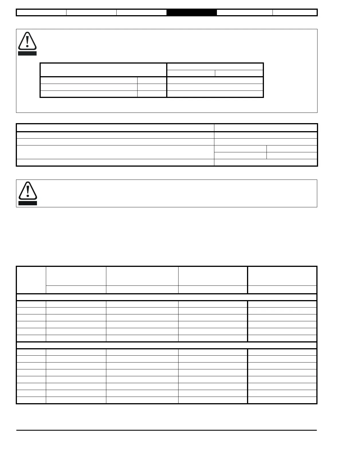
Table 4-10 Compact braking resistor data
4.8.2 External braking resistor
When a braking resistor is to be mounted outside the enclosure, ensure that it is mounted in a ventilated metal housing that will perform the following
functions:
• Prevent inadvertent contact with the resistor
• Allow adequate ventilation for the resistor
When compliance with EMC emission standards is required, external connection requires the cable to be armored or shielded, since it is not fully
contained in a metal enclosure. See section 4.10 EMC (Electromagnetic compatibility) on page 61 for further details.
Internal connection does not require the cable to be armored or shielded.
Table 4-11 Minimum resistance values and peak power rating for the braking resistor at 40 °C (104 °F)
* Resistor tolerance: ±10 %. The minimum resistance specified are for stand-alone drive systems only. If the drive is to be used as part of a common
DC bus system different values may be required. See Braking resistor software overload protection on page 60.
Braking resistor overload protection parameter settings.
Failure to observe the following information may damage the resistor.
The drive software contains an overload protection function for a braking resistor, this function is enabled at default to protect the compact
resistor.
Below are the parameter settings.
For more information on the braking resistor software overload protection, see Pr 10.030, Pr 10.031 and Pr 10.061 full descriptions in the
relevant Control User Guide.
Parameter
All frames
200 V drive 400 V drive
Braking resistor rated power Pr 10.030 50 W
Braking resistor thermal time constant Pr 10.031 2 s
Braking resistor resistance Pr 10.061 70
Parameter All frames
Part number 3470-0152
DC resistance at 25 °C 70
Peak instantaneous power over 1 ms at nominal resistance
200 V 400 V
2.2 kW 8.7 kW
Average power over 60 s 50 W
Thermal protection
When an external braking resistor is used, it is essential that a thermal protection device is incorporated in the braking resistor circuit.
Model
Minimum resistance*
(Pr 10.061)
Peak power rating
Continuous power rating
(Maximum Pr 10.030 setting)
Maximum braking resistor
thermal time constant
(Pr 10.031)
Ω kW kW s
200 V
01200022 25 6 2 2
01200040 25 6 2 2
01200065 25 6 2 2
02200090 13 11.1 3.7 2
02200120 13 11.1 3.7 2
03200160 10 15 5 2
400 V
01400015 106 5.7 1.9 2
01400030 106 5.7 1.9 2
01400042 106 5.7 1.9 2
02400060 36 16.8 5.6 2
02400080 36 16.8 5.6 2
02400105 36 16.8 5.6 2
03400135 26 22.8 7.6 2
03400160 26 22.8 7.6 2