Safety information Product information Mechanical installation Electrical installation Multi axis system design Technical data
68 Digitax HD M75X Series Installation and Technical Guide
Issue Number: 5
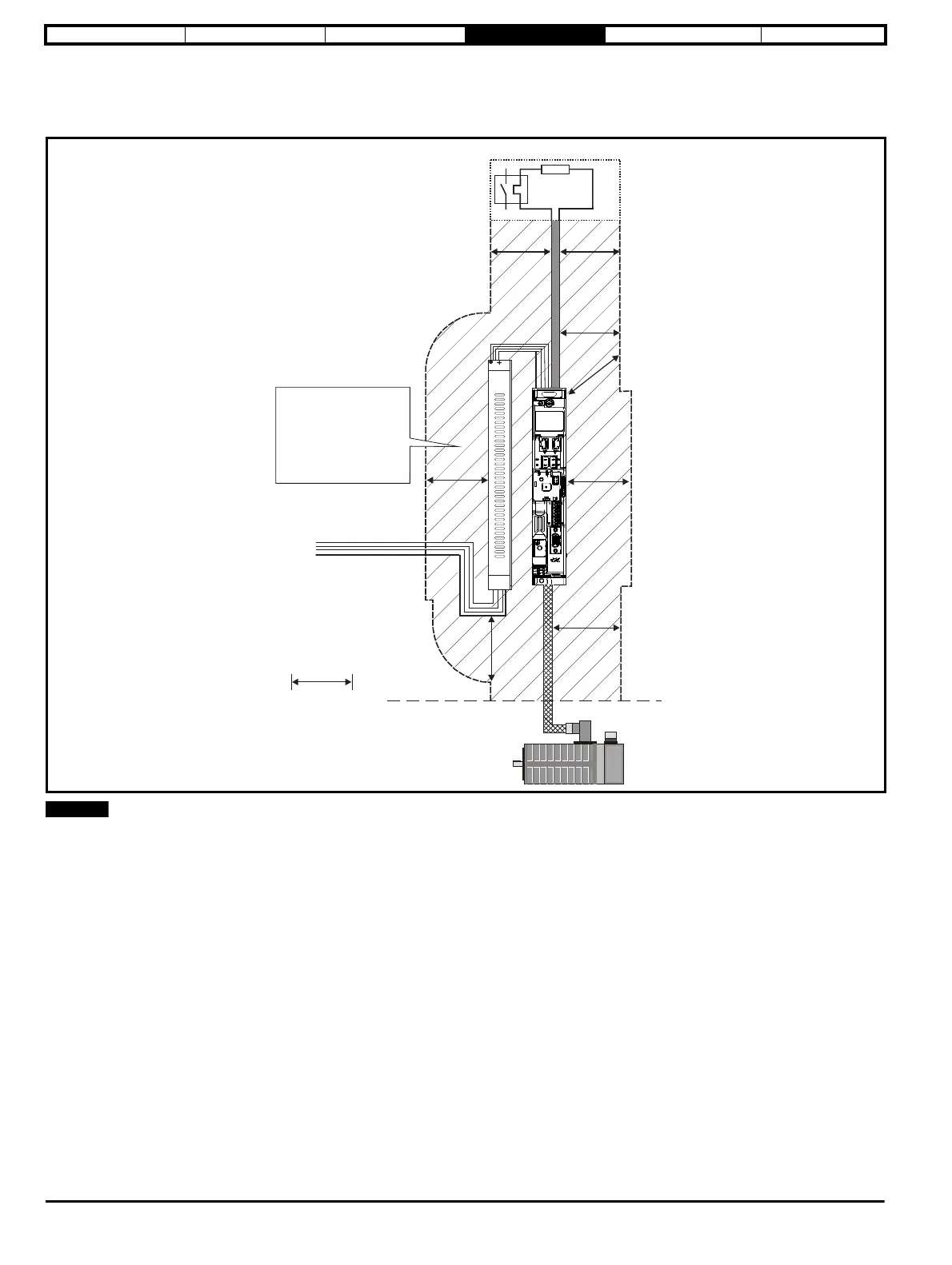
4.10.5 Cable layout
Figure 4-17 indicates the clearances which should be observed around the drive and related ‘noisy’ power cables by all sensitive control signals /
equipment.
Figure 4-17 Drive cable clearances
Any signal cables which are carried inside the motor cable (i.e. motor thermistor, motor brake) will pick up large pulse currents via the cable
capacitance. The shield of these signal cables must be connected to ground close to the motor cable, to avoid this noise current spreading through
the control system.
Optional braking resistor and overload
Do not place sensitive
(unscreened) signal circuits
in a zone extending
300 mm (12”) all around the
Drive, motor cable, input
cable from EMC filter and
unshielded braking resistor
cable (if used)
300mm
(12in)