Safety information Product information Mechanical installation Electrical installation Multi axis system design Technical data
86 Digitax HD M75X Series Installation and Technical Guide
Issue Number: 5
Each Digitax HD M75X drive has its own inrush current limitation circuit; therefore no additional inrush circuit is required.
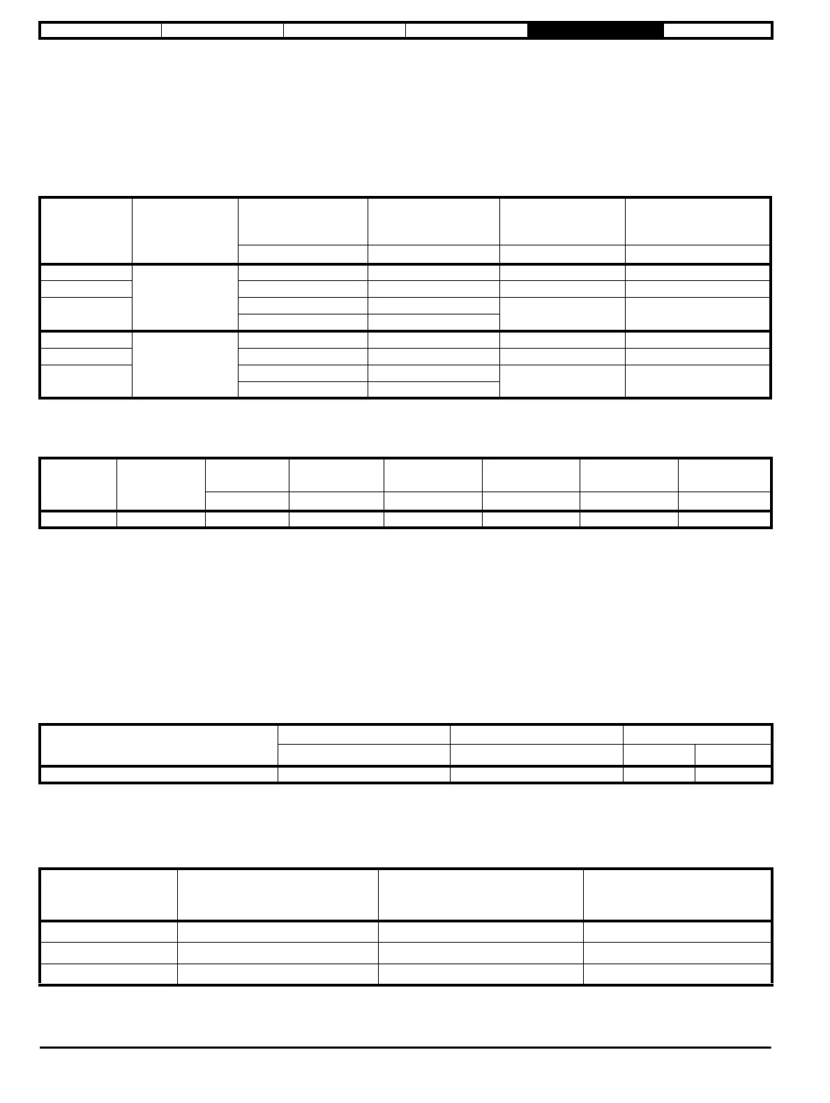
The worst case output power requirement for the whole system must be compared with the maximum continuous AC input power of the drive chosen
with the AC connection (Digitax HD M75X rectifier), refer to Table 5-1 Multi axis AC input ratings.
To prevent the Digitax HD M75X rectifier from being overloaded, the worst case system output power demand from all axes, must not
exceed the maximum continuous AC input power of the Digitax HD M75X rectifier at any time.
Where the maximum continuous AC input power of the Digitax HD M75X rectifier is exceeded, additional frame blocks will be required.
Table 5-1 Multi axis AC input ratings
* An AC line reactor can be used to extend the power rating of the drives, a suitable line reactor is available from the supplier of the drive, refer to
Table 5-2.
Table 5-2 Digitax HD M75X line reactor
Maximum frame block capacitance
When creating a frame block with Digitax HD M75X drives of multiple frame sizes, the maximum frame block capacitance (b) that the Digitax HD
M75X rectifier can support should be greater than the sum of all the individual internal drive DC capacitance values (a) within the same frame block.
If more drives are required for an application than a single frame block will allow, then multiple separate frame blocks each with an individual Digitax
HD M75X rectifier can be created.
Input cable and fusing
No supplemental DC fuses are required for this type of configuration.
When a Digitax HD M75X drive is used as a AC supply for a frame block, only AC branch protection fuses are required. The maximum fuse which can
be used to protect the system is given in Table 5-3. Smaller fuses and input cables can be used provided the fuse is from the same range and
dimensioned for the required input power. If the input cable is smaller than that listed in Table 5-3 the protection fuse must be reduced accordingly.
Table 5-3 Maximum fuse and minimum cable size for AC converter
When the AC input power is known, the following formula can be used to estimate the suitable input current for cable and fuse selection.
Input current (A)= a x P(kW)
2
+b x P(kW)+c
Where constants a, b and c are given in Table 5-4:
Table 5-4 Input current equation constants
Digitax HD
M75X frame
size
Voltage range
Max continuous AC
input power
Maximum input current
Internal drive DC
capacitance
(a)
Maximum frame block
capacitance when AC
source (b)
kW A uF uF
1
200 V
4 23.2 580 5800
2 5.3 35.4 1160 4640
3
6.3 37.9
1880 3760
10* 37.9
1
400 V
6.5 23.9 110 1900
2 8.7 34.5 290 2030
3
10 39.1
470 2210
13* 39.1
Part
number
Line reactor
designation
Line reactor
current rating
Inductance Weight Length Width Height
Amh kg mmmmmm
4401-0236 INL4013 32 0.48 4.9 102 156 146
Model
Fuse rating Fuse rating Input cable size
IEC class gG UL class J
mm
2
AWG
All 40 40 6 8
Constant 200 V drives, 3 phase 400 V drives, 3 phase 200 V drives, single phase
a -0.55 -0.2 -0.5
b9.7 6 11
c0.2 0.5 0