NE200&300 Quick Start Guide
16
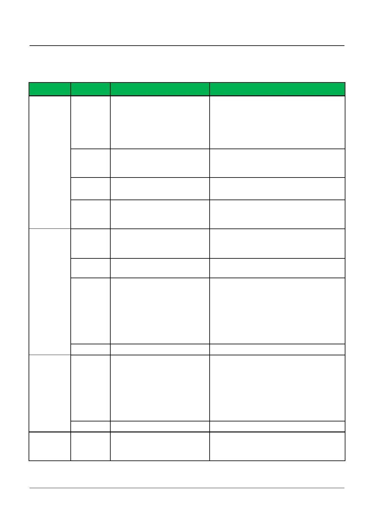
4.1.1 Functions of Control Circuit Terminals
Standard configuration of control circuit terminals
Type
Termina
Terminal function Technical specification
Digital
input
&
output
X1
~
X5
Multi-functional input
terminals 1
~
5
Optical-isolator input
Frequency range:
:
0
~
200Hz
Voltage range: 0
~
12V
Y1 Open collector output
Optical-isolator output
maximum output current: 50mA
Output voltage range
:
0
~
24V
GND Terminal ref. grounding
24V 24V
24V±5%, Maximum load :200mA,
with overload and short circuit
Analog
input
10V
Analog input reference
voltage
Open circuit voltage up to 11V;
Maximum output 30mA
AI1 Analog input channel 1
Input Voltage range
:
0
~
10V
Input impedance
:
100kΩ
AI2 Analog input channel 2
Input Voltage range
:
0
~
10V
Input impedance
:
100kΩ
Input current range
:
0
~
30mA
Current Input impedance
:
500Ω,
0~20mA or 0~10V analog input
can be selected through DIP
switch SW1
GND Terminal ref. grounding
Analog
output
AO Analog output 1
0
~
20mA: Allowed load
impedance 200~500Ω
0
~
10V: Allowed load impedance
≥1kΩ.
With SC protection; 0~20mA or
0~10V analog output can be
selected through DIP switch SW2
GND Analog grounding
Relay
output
TA/TB/
TC
Relay output 1
TA
-
TB
:
NC; TA
-
TC
:
NO
Contact capacity
:
250VAC/1A
,

 Loading...