NE200/300 Series Drive User Manual
Chapter 6 Parameter description 155
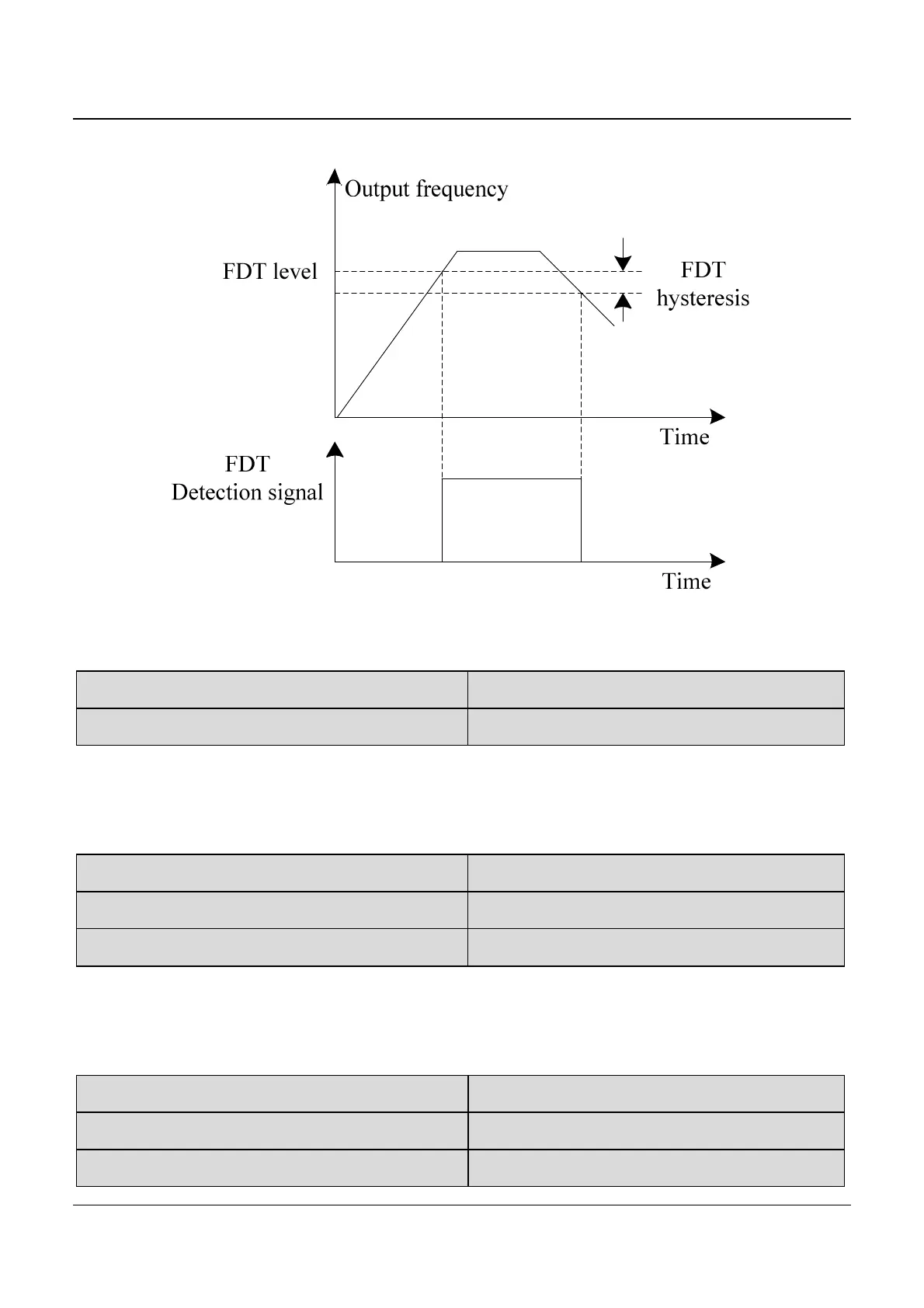
Fig.6-21 FDT level and lag diagram
F7.10 Up detection frequency Range: 0.00~550.0Hz【50.00Hz】
F7.11 Down detection frequency Range: 0.00~550.0Hz【0.00Hz】
These two parameters define the detection trigger frequency value for
increasing stage and decreasing stage respectively.
F7.12 Torque detection reference Range: 0.0~200.0%【100.0%】
F7.13 Preset Count value Range: 0~9999【0】
F7.14 Preset Timing value Range: 0.0~6553.0s【0.0s】
The above parameters define the detection trigger value for torque
arrival detection, counting arrival detection, and timing arrival detection.
F7.16 AI1 compare threshold 1 Range: 0.00~10.00V【0.00V】
F7.17 AI1 compare threshold 2 Range: 0.00~10.00V【0.00V】
F7.18 Analog compare hysteresis Range: 0.00~30.00V【0.20V】



 To Next Page