- A ・ -
logo_Q0650_forGraphic
071004_Gdesign_ito
VBA21001-R.3753.A
・
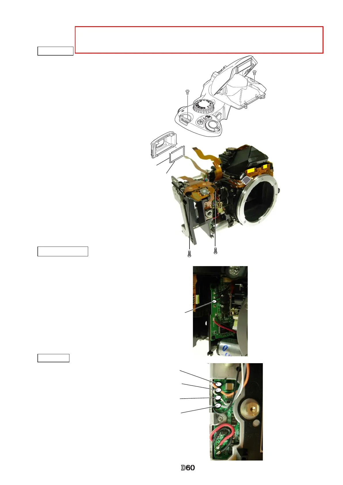
Mount the rubber eyecap (#B271).
・
Watching the wires and FPCs, mount the top cover.
・
Tighten two screws (#5737) and two screws (#635).
Top cover
When the AE-CCD positioning is adjusted, solder the only four wires that connected from the
top cover to SB-PCB. Then, make a temporary assembly without mounting the rubber eye-
cap (#B271), and assemble up to Page A27.
・
Solder the four wires
(connected from Top
cover).
・
Solder the wire (connected from Top cover).
DC/DC PCB unit
SB PCB
Orange: Top cover
White: Top cover
Gray: Top cover
Black: Top cover
Black: Top cover
#B271
#5737×2
#635×2
#486×2
#487×2