105Service Manual – SC5000 22 - Steering System
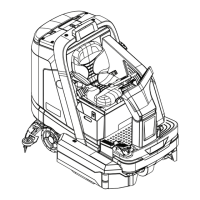
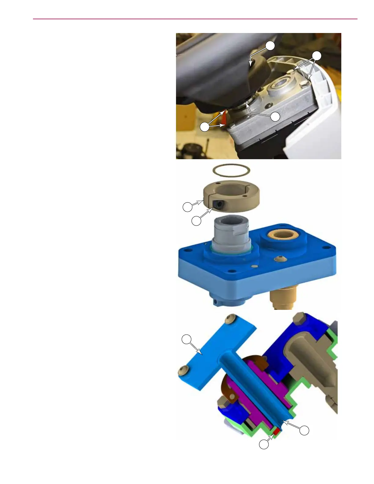
9. Remove the two screws (K, not visible) that
secure the steering wheel to the clamping
collar (M) of the steering box, and remove
the wheel.
10. Remove the four screws (L) that secure the
steering box to the steering column frame,
and slide the box out of the U-joint to remove
it.
11. Reassemble the machine incorporating the
procedures listed below.
Steering Wheel Alignment
The steering wheel bolts onto a clamping collar
of the steering offset box (see step 9 above).
This clamping collar is retained by a retaining
ring, but also clamps down on the steering shaft
to prevent rotation. If the clamping screw (N)
is loosened, the collar can be rotated, but not
removed.
With the drive wheel pointing forward, one of the
spokes of the steering wheel should be pointing
straight downward. If the steering wheel is not
properly lined up, loosen the clamping screw (N),
rotate the steering wheel, and then retighten the
clamping screw.
Securing the User Interface Mount
12. Insert the user interface mount assembly
(G and H) into the gearbox until the shaft
(H1) bottoms out in the gear box.
13. If the setscrew (F) does not have a thread
lock patch, apply Loctite 242 or 243 to the
setscrew.
14. Gradually tighten the setscrew while
rotating the mount (H) to feel for the center
of the shaft-at. Once the shaft-at center
is found (the mounting plate is aligned
horizontally), tighten the setscrew to 53±5
in-lbs (6±0.6 Nm).
L
L
K
M
N
M
H
F
H1
 Loading...