Service Manual: SC750, SC800, SC 750 ST, SC800 ST
Form Number 56043150 Page 40
8. Remove the electrical panel cover and place on a work bench.
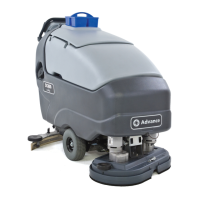
9. Remove the 5 screws securing the switch panel interface and carefully turn the cover over.
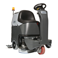
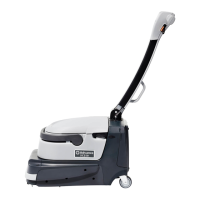
10. Remove 4 screws securing circuit board (Main Machine Controller) to cover. Be careful not to lose the 4 plasc
spacers that go between the circuit board and the cover.
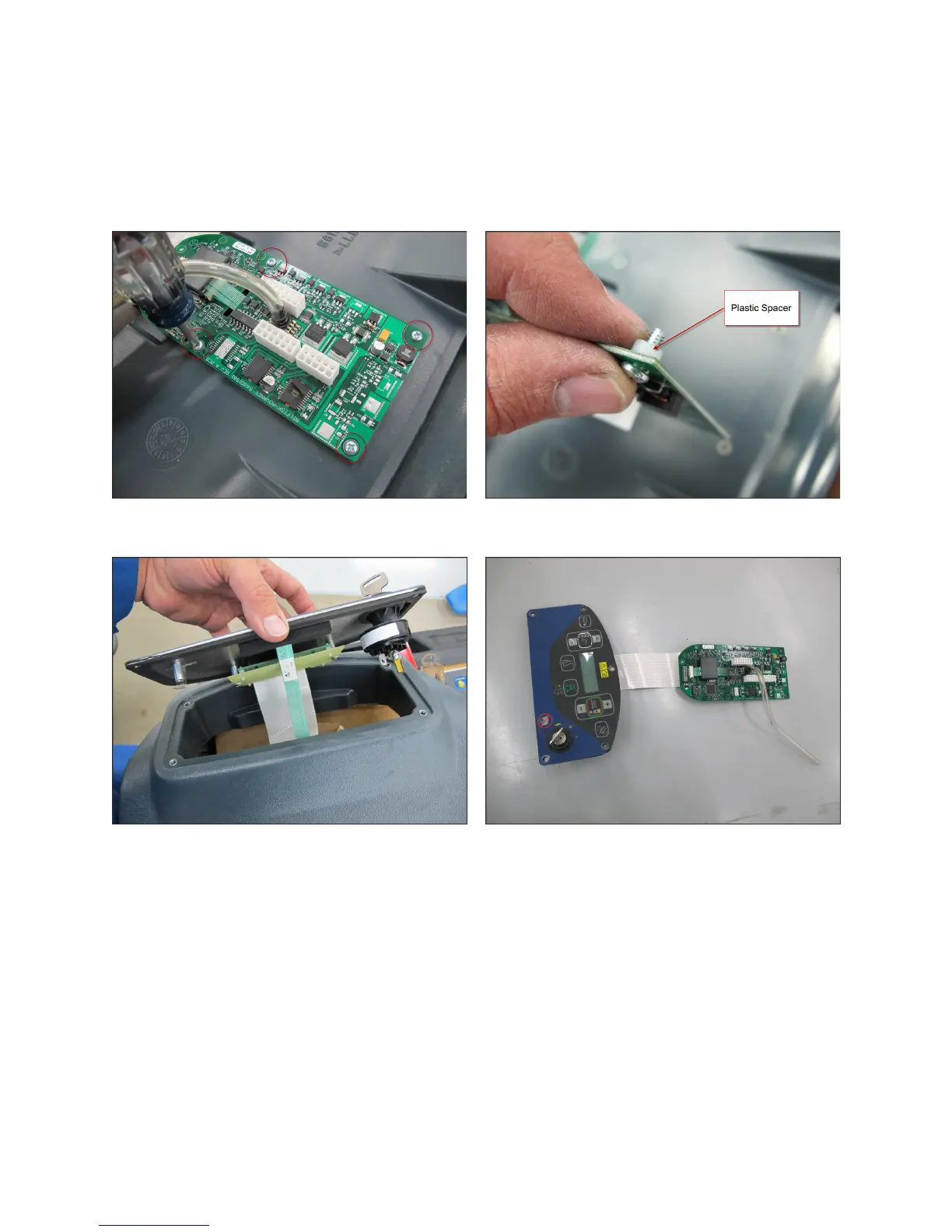
11. Remove the control switch interface panel and circuit board together through the cover opening.
12. Reassemble in reverse order, taking care not to damage the printed circuit ribbons used to connect the circuit
board to the control switch interface panel. If you did not drain the soluon tank earlier, you must do so before
connecng the pressure sensor hose in order for the soluon level “gauge” to work properly.
 Loading...