Service Manual: SC750, SC800, SC 750 ST, SC800 ST
Form Number 56043150 Page 70
Recovery System
Functional Description
The job of the recovery system is to remove the dirty water from the oor and store it in the recovery tank. The dirty
water is then disposed of. Dirt and water are lied o the oor into the recovery tank by airow created by a vacuum
motor. The wastewater and air enter the vacuum system at the squeegee tool, through notches in the front squeegee
blade. The air and wastewater move through the squeegee vacuum hose at high speed unl it reaches the recovery
tank. The heavier water falls to the boom of the recovery tank. The airow connues through the vacuum fan inlet
port, vacuum motor and exhaust port. A debris tray inside the recovery tanks helps to redirect the water downward and
catches large parcles. No wastewater ever actually moves through the vacuum motor, just the working air. A oang
ball in a cage seals o the vacuum port when the tank is full to protect the vacuum motor from water ingeson. When
the oat ball seats, the amp draw of the motor is reduced and the shuts o the vacuum motor. The squeegee is raised
and lowered manually using the squeegee li lever. Springs apply downward pressure on the squeegee.
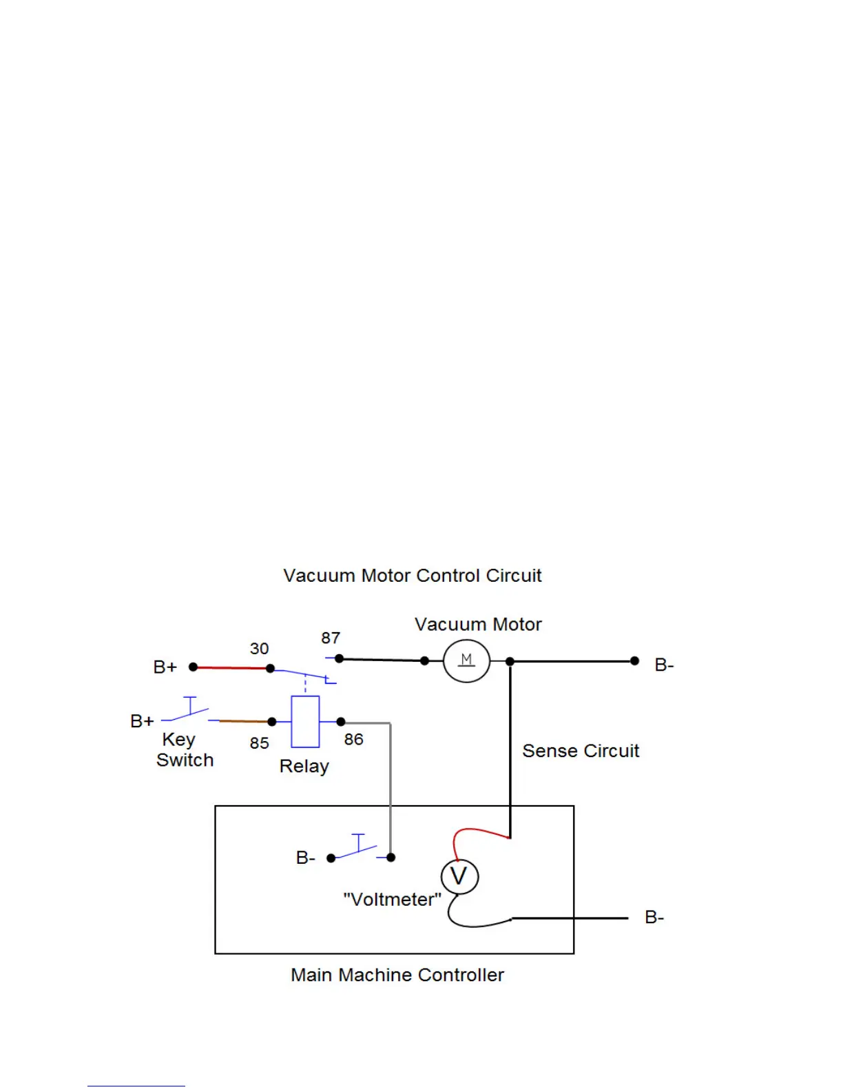
Here is how the vacuum motor circuit works. The relay winding is fed baery voltage on terminal 85. The other side of
the relay coil (terminal 86) is connected to a switch inside the controller. To energize the relay, the controller closes the
switch which completes the path to B-. The relay contact terminal 30 is connected to B+. When the relay is energized, the
contacts close connecng 30 to 87 which sends baery voltage to the vacuum motor. Since the other side of the motor is
connected to baery negave, the motor turns on. The also monitors the current draw of the vacuum motor via a “vacu-
um motor sense” wire. The controller has an internal “voltmeter” that measures the voltage dierence (drop) between
the sense wire and baery negave. A calibrated ground wire of a specic size and length is used for the motor ground.
At a given amperage ow, there is a correlang voltage drop. As the amperage increases the voltage drop also increases.
The controller translates the voltage drop measured into amperage.
 Loading...