Main Broom System 159Service Manual – SW4000
Main Broom System
Functional Description
By using the left lever on the dashboard the main broom support system lowers, because it is released by
a metal cable; the broom is kept pressed to the ground by two gas springs that ensure the contact with the
ground at all times.
The electric motor transmits the motion to the main broom by means of a drive belt connected to an hexagonal
driver that supports the broom.
The machine must be moving otherwise the main broom motor does not run.
The front skirt lifting pedal allows to collect medium size waste materials (cans, boxes, etc.). The front skirt
must be lifted only when necessary, because it affects the operation of the dust control system.
The main broom motor (M4) is supplied by the electromagnetic switch (ES1) and protected by the fuse (FA).
The electromagnetic switch (ES1) is activated by the dashboard electronic board (EB2) according to the infor-
mation received by: sensor (S2) (main broom control lever position), machine moving signal (information that
EB2 receives from EB1), lifted hopper signal, battery voltage (see Dashboard Electronic Board Specications,
step d).
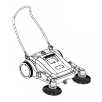
The fuse (FA) activates in case of short circuit or blocked rotor, but in case of overload, the dashboard elec-
tronic board (EB2) reads the voltage drop on the fuse, thus deactivating ES1 before the fuse can activate (see
Main Broom Motor Protection, in Dashboard Electronic Board Specications). The activation of an electronic
protection is indicated by the main broom overload warning light (A).
A
P200235
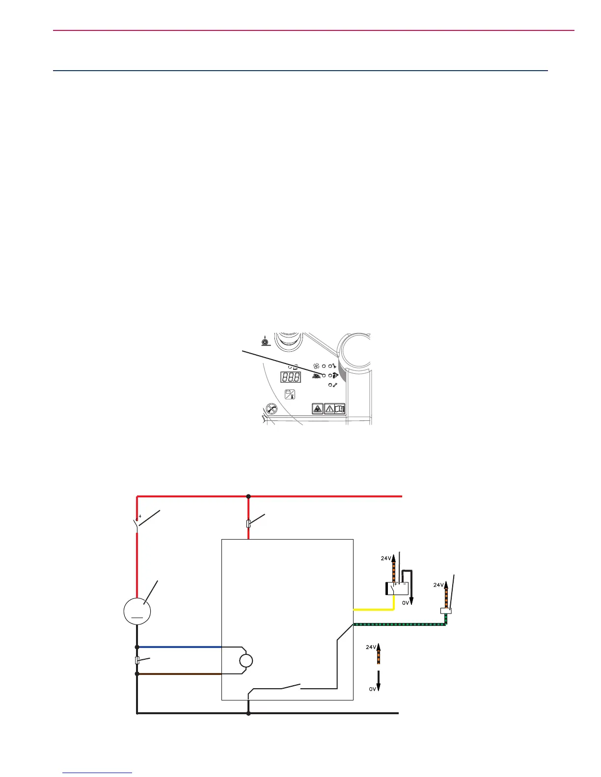
Wiring Diagram
CONTROL PANEL ELECTRONIC BOARD (EB2)
J1.1 - Electronic board power supply +
J1.4 - Broom fuse voltage drop reading +
J1.5 - Broom fuse voltage drop reading -
J1.2 - Broom activation lever signal
J1.10 - Broom electromagnetic switch power supply
J1.9 - Electronic board power supply -
MAIN BROOM
ELECTROMAGNETIC
SWITCH (ES1)
DISPLAY ELECTRONIC
BOARD FUSE (F3)
MAIN BROOM
MOTOR
MAIN BROOM
FUSE (FA)
MAIN BROOM
ELECTROMAGNETIC
SWITCH (ES1)
MAIN BROOM LEVER
SENSOR (S2)
POSITIVE SIGNAL
(FROM MACHINE ON “K4”)
BATTERY NEGATIVE TERMINAL
V
M4
P200168

 Loading...