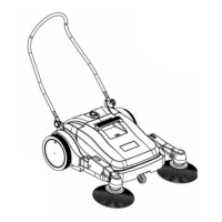
Dust Control System 43Service Manual – SW4000
Dust Control System
Functional Description
The dust raised in the compartment of the main broom, is collected in the rear cargo area by a ow of air gener-
ated by the dust control system.
The lter located between the vacuum system and the hopper, retains dirt which is then conveyed through a
feedbox into the hopper itself.
The operation of the system depends on the activation of the main broom.
By deactivating the main broom, the dust control system turns off automatically.
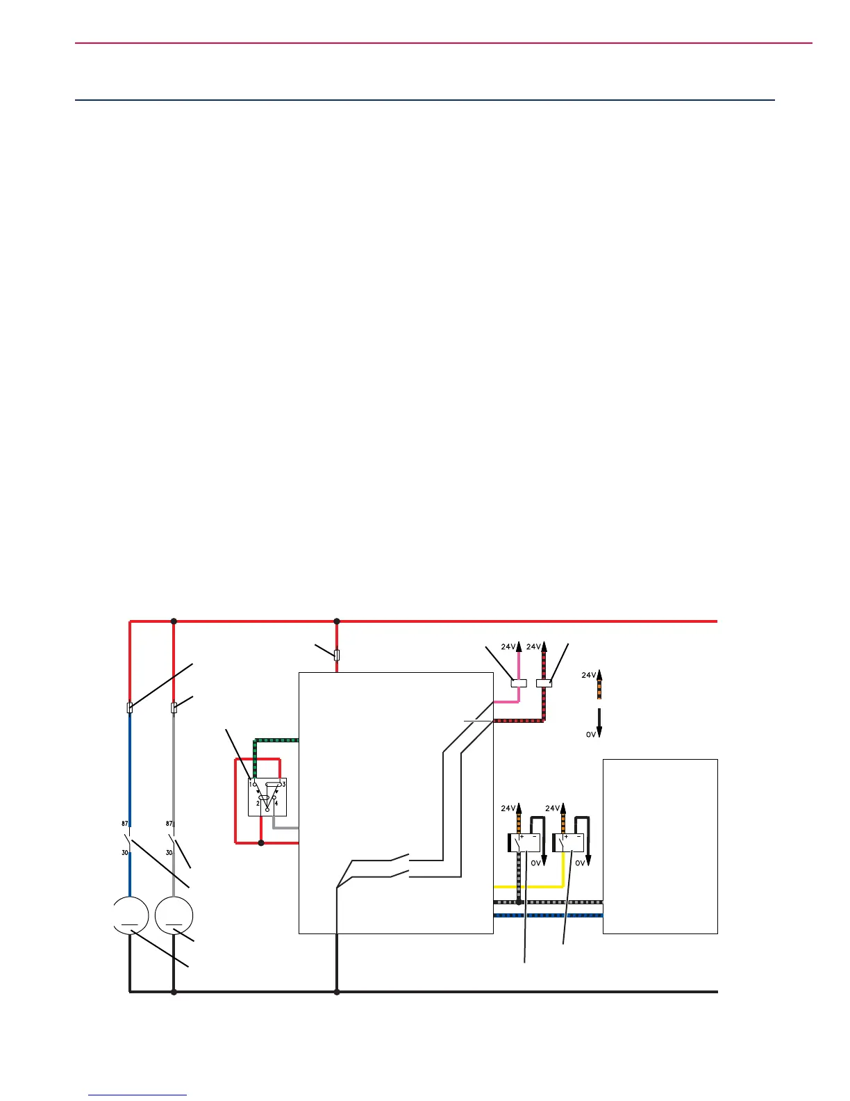
There is a vacuum system motor (M1) which is powered by the relay (K1) and protected by the fuse (F1).
The relay (K1) is directly controlled by the dashboard electronic board (EB2) according to the information re-
ceived by the vacuum system/lter shaker switch (SW3), by the sensor on the broom activation lever (S2), by
the machine moving signal received by the drive system electronic board(EB1) and by the lifted hopper sensor
(S1).
Normally the vacuum function is turned on when the main broom is lowered with the lever; it can, however,
be turned on or off independently with the push-button SW3, it turns off when the machine is stopped, when
the hopper is lifted and during activation the electric lter shaker.
There is an electric lter shaker motor (M2) which is powered by the relay (K2) and protected by the fuse (F2).
The relay (K2) is directly controlled by the dashboard electronic board (EB2) according to the information re-
ceived by the vacuum system/lter shaker switch (SW3): When the button is activated for a cycle of 20 seconds
during which it is driven 0.5 sec ON and 0.5 sec. OFF for continuously modulating the number of revolutions
and the resulting vibration frequencies of the lter.
The vibrating motor shakes the lter allowing dirt trapped in the folds of the same to fall by gravity into the
hopper.
This reduces lter maintenance and helps to maintain proper airow through the lter.
Wiring Diagram
CONTROL PANEL ELECTRONIC
BOARD (EB2)
DRIVE SYSTEM
ELECTRONIC BOARD (EB1)
VACUUM
SYSTEM FUSE (F1)
FILTER SHAKER
FUSE (F2)
DISPLAY ELECTRONIC
BOARD FUSE (F3)
FILTER SHAKER/VACUUM
SYSTEM SWITCH (SW3)
VACUUM SYSTEM MOTOR
FILTER SHAKER MOTOR
VACUUM
SYSTEM RELAY (K1)
VACUUM SYSTEM RELAY (K1)
FILTER SHAKER RELAY (K2)
FILTER SHAKER RELAY (K2)
J1.11 - Vacuum system relay power supply
J1.1 - Electronic board power supply +
J2.2 - Vacuum system activation signal
J2.1 - Control panel switch power supply (+)
J2.7 - Machine moving signal
J1.9 - Electronic board power supply -
POSITIVE SIGNAL
(FROM MACHINE ON “K4”)
BATTERY NEGATIVE TERMINAL
J1.12 - Filter-shaker relay power supply
J1.18 - Machine moving signal
J2.3 - Filter-shaker activation signal
J1.8 - Lifted hopper signal
J1.2 - Broom activation lever signal
HOPPER LIFTING
SENSOR (S1)
MAIN BROOM
LEVER SENSOR (S2)
J2.11 - Lifted hopper input
M2M1
P200102

 Loading...