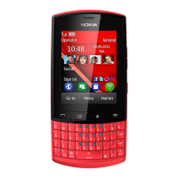
User interface
User interface
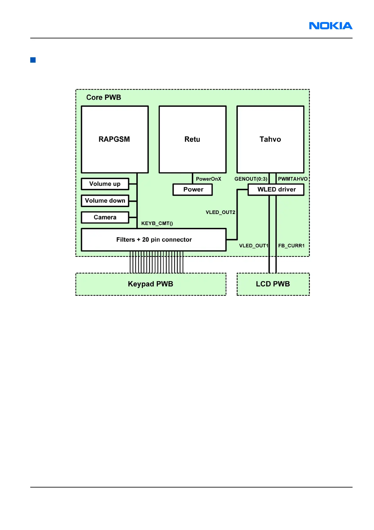
Figure 58 User interface block diagram
Display and display backlight
The display is controlled by RAPGSM, with signal conditioning by serial resistors.
Logic power supply (1.65V-1.95V) is connected to VIO and driver power supply (2.3V-2.9V) is connected to
VAUX.
The display includes four white LEDs for display backlights inside of the display module. Display backlight
current is monitored using LED driver feedback input
Keyboard and keyboard backlight
This phone has a specific keyboard PWB. Most keys are placed here. Camera, Power and Volume up/down are
placed on the main board/Core PWB.
RM-70
System module Nokia Customer Care
Issue 1 COMPANY CONFIDENTIAL Page 8 –15
Copyright © 2005 Nokia. All rights reserved.