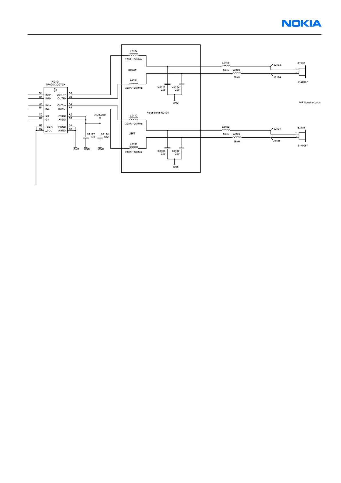
Figure 62 Internal speaker circuitry
External earpiece
All galvanic accessories are connected to the system connector (Pop-Port™).
The accessory audio mode is automatically enabled/disabled during connection/disconnection of dedicated
phone accessories.
Retu ASIC provides two output channels in either single-ended or differential format. Retu ASIC outputs XearL
and XearLC form the left channel audio output, and XearR and XearRC the right channel audio output. XearLC
and XearRC are the ground pins if the output works in a single-ended operation.
In the Pop-Port™ side, HSEAR P and HSEAR N form the left channel output, and HSEAR R P and HSEAR R N the
right channel output. Respectively, HSEAR N and HSEAR R N are the ground pins if the output works in a single-
ended operation.
Analogue switches are in the Xear lines to attenuate the headset signal level in IHF mode, when headset is
inserted. The attenuation is about 15 dB.
Vibra circuitry
Vibra is used for vibra-alarm function.
The vibra motor is connected to the Retu ASIC VibraP and VibraN Pulse Width Modulated (PWM) outputs.
RM-70
System module Nokia Customer Care
Issue 1 COMPANY CONFIDENTIAL Page 8 –19
Copyright © 2005 Nokia. All rights reserved.