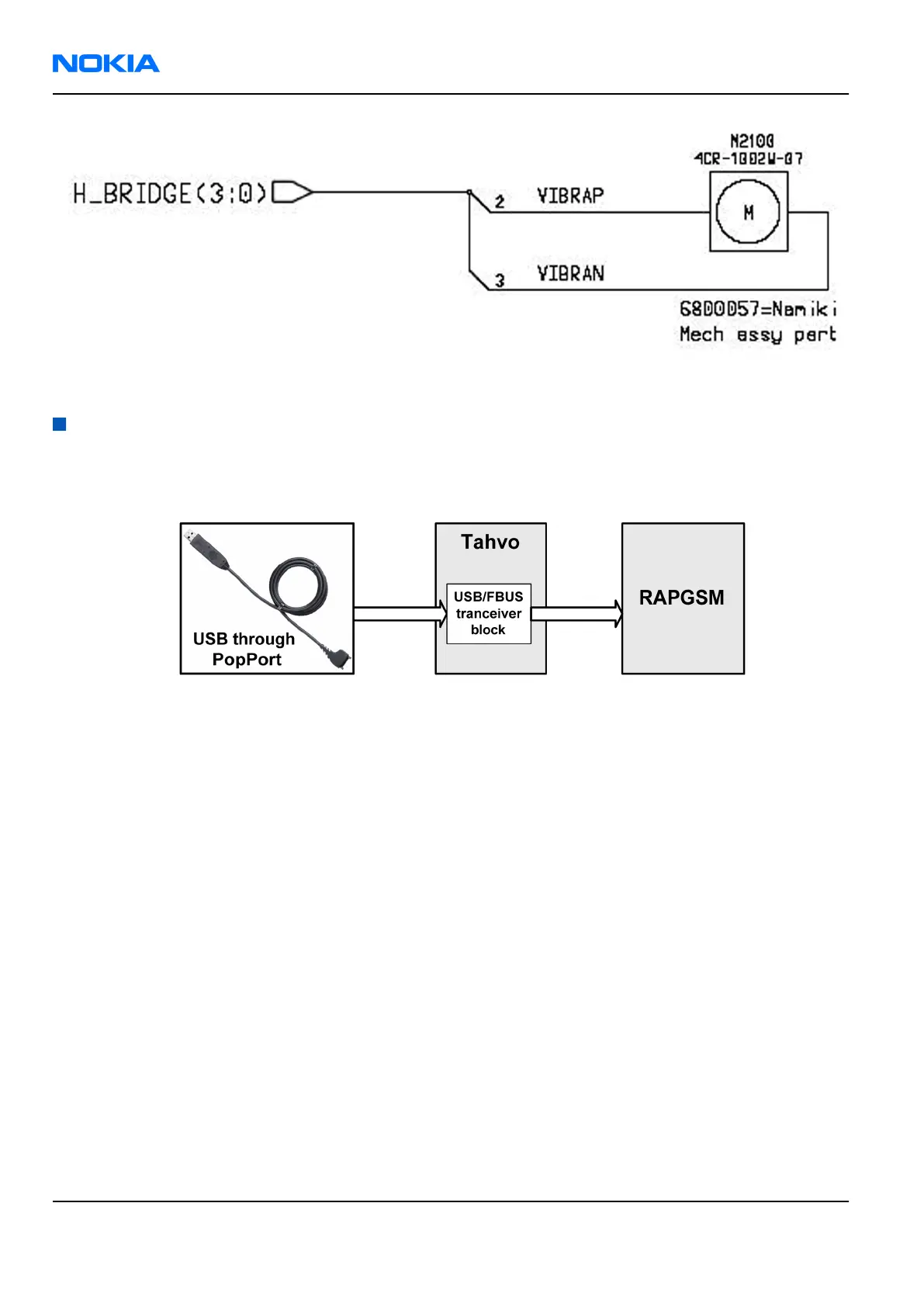
Figure 63 Vibra circuitry
Connections
USB interface
USB (Universal serial bus) provides a wired connectivity between host PC and peripheral devices.
Figure 64 USB interface to engine
The Nokia USB device solution is supported using the Wireless 2 Function Controller (W2FC) core. This core is
included in the RAPGSM. The core completes several USB functions automatically and is controlled by the
MCU. .
The USB signal ESD protection and line matching resistance, and USB pull-up resistor is included to the USB
ASIP. This component also includes ESD protection for VOUT and ACI Pop-Port pins.
The USB solution is also compatible with USB 2.0, with a full speed of 12 Mbps.
Bluetooth
Bluetooth provides a fully digital link for communication between a master unit and one or more slave units.
This bluetooth solution is a single chip solution. The baseband interface to the bluetooth has a separate
PCMbus for audio giving in total 12 connections;
• 4 pins used for UART (data)
• 4 pins for PCM audio and
• 4 pins for control (Host wake-up, BT wake up, BT reset and PURX).
Bluetooth connects to RAPGSM on the GENIO and GPIO busses.
The Bluetooth module is provided with power from VBat.
Bluetooth is enabled by PURX, which is an internal Retu reset signal. This signal is high whenever the phone
is powered on.
RM-70
Nokia Customer Care System module
Page 8 –20 COMPANY CONFIDENTIAL Issue 1
Copyright © 2005 Nokia. All rights reserved.