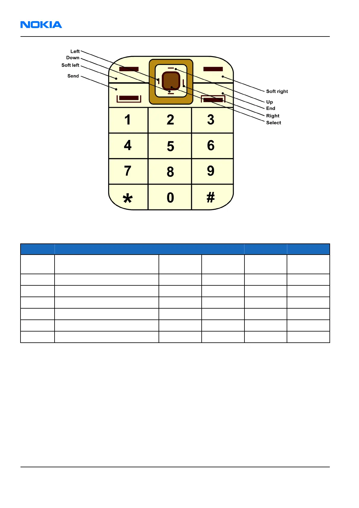
Figure 59 Keyboard layout
Table 15 Key signal matrix
GENIO 39 40 41 42
KEYB_CMT8
(COL0)
KEYB_CMT9
(COL1)
KEYB_CMT10
(COL2)
KEYB_CMT11
(COL3)
32 KEYB_CMT0 (ROW0) Soft left Soft right Left Right
33 KEYB_CMT1 (ROW1) Select Send Up Down
34 KEYB_CMT2 (ROW2) 7 2 3 8
35 KEYB_CMT3 (ROW3) 5 Camera 1 6
36 KEYB_CMT4 (ROW4) 9 * Vol+ #
37 KEYB_CMT5 (ROW5) End 0 Vol- 4
There are four white LEDs placed on the keyboard PWB for illumination of the keyboard. Supply source for
backlights is implemented using an external white LED driver. The driver increases battery voltage up to 18V.
The white LED driver is enabled by Tahvo’s PWM300 output. PWMTAHVO (PWM300) is SW controlled pulse
width modulated (PWM) output.
Keyboards backlight LEDs are current controlled and switchable via TAHVO GENOUT3.
Swivel switch
The detection of the position of the swivel is made through two Hall sensors, connected to GENIO44, and two
magnets. The magnets are positioned in the upper block in the swivel construction. The output of the Hall
sensor is connected to GND.
When the swivel is opened, the applied magnetic field is high. This is sensed by an internal switch, also
connected to GND. When the construction is closed, at least one of the two Hall sensors is fluxed by magnetic
field.
RM-70
Nokia Customer Care System module
Page 8 –16 COMPANY CONFIDENTIAL Issue 1
Copyright © 2005 Nokia. All rights reserved.