Hardware description
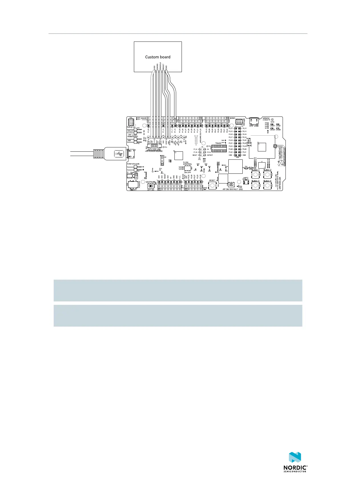
Figure 30: Connecting an external board to P20
It is recommended to power the external board separately from the DK. The voltage on the external board
must match that of the DK. When the DK is powered through the USB connector, the voltage is 3V.
When the interface MCU detects the voltage of the external board on pin 3 (SWD1_VTG) of P20 it
programs or debugs the target chip on the external board instead of the onboard nRF5340 SoC.
If it is inconvenient to have a separate power supply on the external board, the nRF5340 DK can supply
power through pin 2 (VDD) of P20. The connection is shown with a grey outline in Figure 30: Connecting
an external board to P20 on page 30. If the interface MCU detects boards connected to both P19 and
P20, it programs or debugs the target connected to P19 by default.
CAUTION: To avoid overloading the power supply and damaging the DK, use VDD and keep the
supply below 100 mA. Do not use a Li-Poly source.
CAUTION: To avoid damaging your board, do not connect a separate power supply to the external
board when VDD of nRF5340 DK is connected to the external board.
The following section includes an illustration of the P20 connector pinout with a description table.
4406_638
30

 Loading...
