3
0−1000 PSI Pressure Transducer and Amplifier
Part 1602989-02
E 2021 Nordson Corporation
Installation
WARNING: Allow only qualified personnel to perform the following tasks. Follow
the safety instructions in this document and all other related documentation.
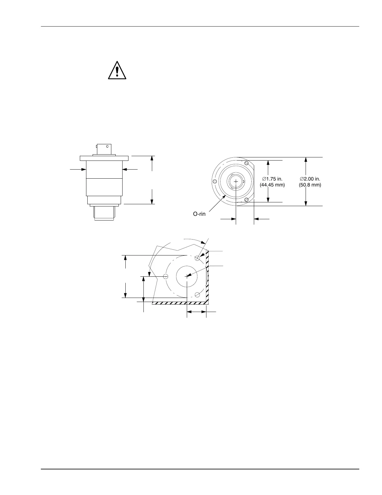
Amplifier Mounting Dimensions
Install the amplifier in an enclosure or panel, using the dimensions in Figure 2 and
the 8−32 seal screws installed in the flange for shipment.
2.40 in.
(61 mm)
1.50 in.
(38.1 mm)
ÎÎÎÎÎÎÎ
ÎÎÎÎÎÎÎ
ÎÎÎÎÎÎÎ
ÎÎÎÎÎÎÎ
ÎÎÎÎÎÎÎ
ÎÎÎÎÎÎÎ
1.75 in.
(44.45 mm)
2.00 in.
(50.8 mm)
O-ring
0.75 in.
(19.05 mm)
1.75 in.
(44.45 mm)
#7 Drill (0.201 in.)
3 Holes
, equally spaced
7/8 in. Hole
(49/64 Min., 1-1/4 in. Max)
120_
1.050 in.
(26.6 mm) Min.
0.80 in.
(20.3 mm) Min.
MOUNTING HOLE DIMENSIONS
AMPLIFIER FLANGE
Figure 2 Amplifier Mounting Dimensions
 Loading...

