Chapter 6 Configuring branch office tunnels 121
Nortel VPN Router Configuration — Basic Features
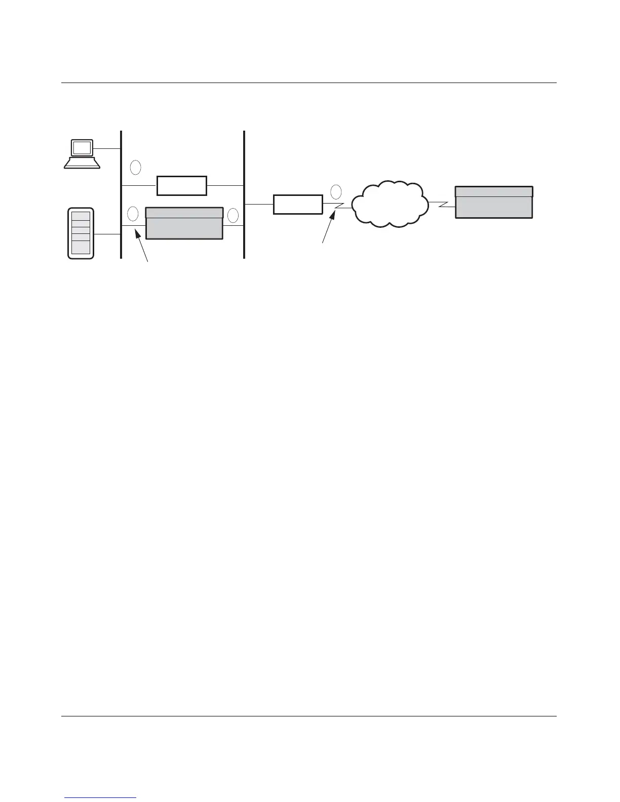
Figure 20 Branch-to-branch with a firewall and a router
In the branch-to-branch illustration, the following interactions take place with a
Nortel VPN Router:
1 The PC sends packets to the default route (the firewall).
2 The firewall redirects the packets to the local Nortel VPN Router branch
office connection.
3 The encapsulated data goes onto the public LAN.
4 The default public LAN route directs the encapsulated data to the remote
Nortel VPN Router branch office connection.
For a Nortel VPN Router that has a WAN link, actions 3 and 4 collapse together,
and the encapsulated data is directed to the remote server.
In a three-Nortel VPN Router topology, the two indirectly connected Nortel VPN
Routers can create tunnels at will as long as each Nortel VPN Router properly
includes all of the local and remote subnetworks and subnetwork masks as
accessible networks. Figure 21 on page 122 shows the relationship between three
Nortel VPN Routers and the local and remote networks that must be configured
for each link to allow indirectly connected branch offices to bring up tunnels at
will. The New York Nortel VPN Router in the middle has two branch office
connections configured.
All connections must have identical encryption settings. However, only adjacent
connections are required to share keys. For example in the following figure, the
Boston − New York connection shares keys and the New York − Cleveland
connection shares keys. Boston and Cleveland are not required to share keys.
LAN
Firewall
Router
Private LAN
Public WAN
PDN
Public LAN
Nortel VPN Router
Nortel VPN Router
1
2
3
4