Do you have a question about the Notifier AIM-200 and is the answer not in the manual?
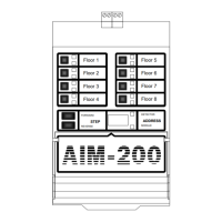
Overview of the AIM-200's role as an interface for the System 5000 Fire Alarm Control Panel.
Details the AIM-200 module's function, communication, and zone mapping capabilities.
Information on using slide-in labels and the device information card file for the AIM-200.
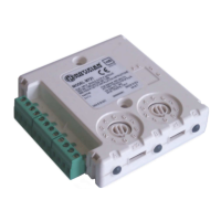
Step-by-step guide for mounting the AIM-200 to the CHS-4 Chassis and connecting ribbon cable.
Instructions for wiring the alarm bus cable between the AIM-200 and the CPU-5000 panel.
Covers wiring for non-redundant, redundant, and isolated-redundant communications loops.
Guidelines for terminating shield drain wires in various conduit configurations.
Explains the role of the ISO-X module in isolating faults on communications loop branches.
Details the specifications and wiring for MMX-1, MMX-2, and MMX-101 monitor modules.
Describes the CMX-2 module for notification appliance circuits and Form-C relays.
Instructions for installing and wiring the BGX-101L addressable manual pull station.
Guide for installing intelligent detectors with BX-501/B501 bases and setting addresses.
Procedure for organizing and inserting the AIM-200 cards into the module for configuration.
Overview of intelligent detectors compatible with the AIM-200, including BX-501 base.
Overview of addressable modules compatible with the AIM-200, such as MMX and CMX series.
Explains the AIM-200's digital display for showing device type, address, and operational status.
Guides the user through the automatic process of detecting and programming loop devices.
Details how to modify existing device configurations and settings within the AIM-200 memory.
Describes the feature for controlling LED status indicators on AIM-200 connected devices.
Procedure for erasing the AIM-200's stored program data and preparing for reprogramming.
Illustrates the default mapping of devices to zones upon initial AIM-200 setup.
How to view the status, type, and sensitivity of individual detectors and modules.
Explains the zone display indicators, switches, and how zones reflect device status.
Setup for CMX-2 modules for general alarm and floor-based activation via zone mapping.
Configuration for CMX-2 modules based on MMX module addresses.
Configuration for CMX-2 modules based on the address of an alarmed intelligent detector.
Calculates the current draw of the AIM-200 and connected devices during non-alarm conditions.
Calculates the current draw of the AIM-200 and connected devices during alarm conditions.
Details on configuring annunciator addresses for AIM-200 points and modules.
| Model | AIM-200 |
|---|---|
| Input Channels | 2 |
| Humidity Range | 10% to 93% non-condensing |
| Compatibility | Notifier ONYX Series |
| Mounting | Surface mount |
| Certifications | UL, FM |