51
Document 15949 Rev. E 4/12/95 P/N 15949:E
Control-by-Detector
-
Control-by-Detector is a useful function for activating sounders in
the same room or location as the alarmed intelligent detector. To set up Control-by-Detector,
set detector address in the range 80-99. Ensure that a CMX-2 module exists with the same
address as the detector, and that the CMX-2 has not been mapped to any zones.
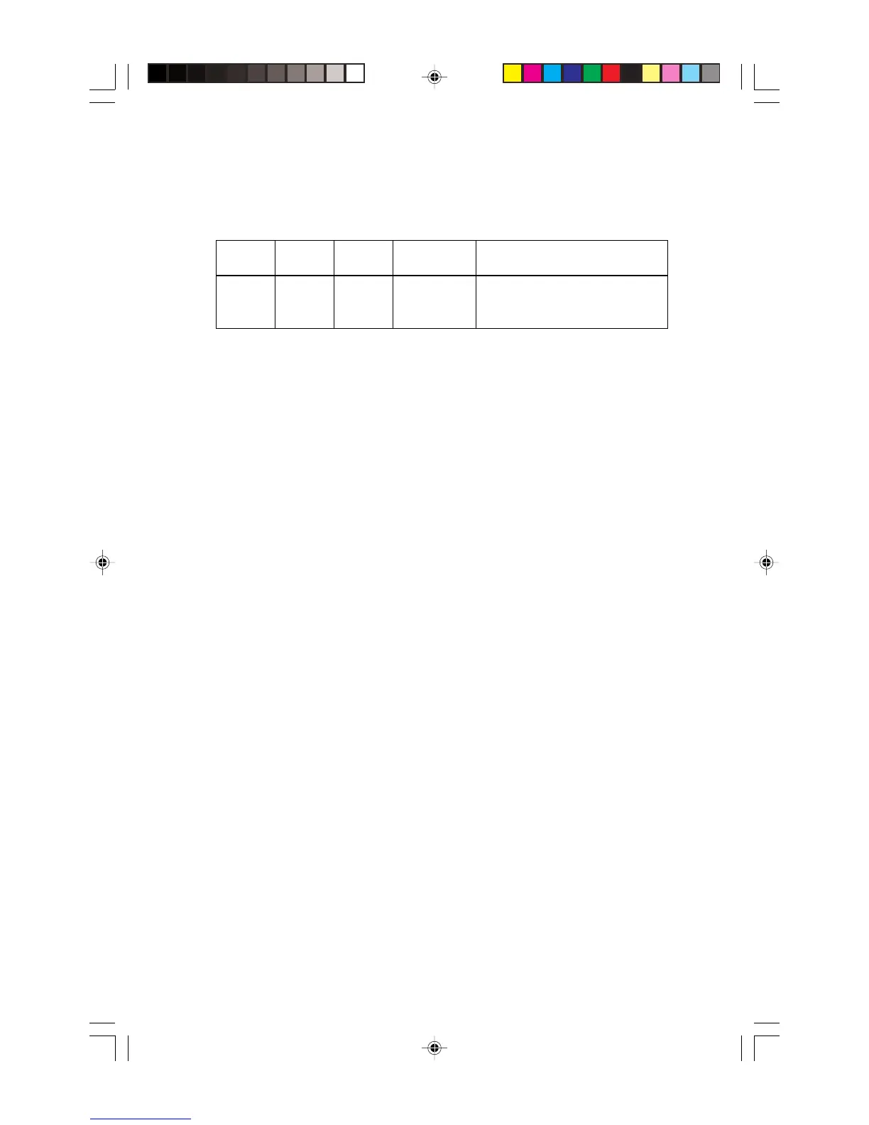
Alarm
From
Detector
Address
CMX-2
Address
CMX-2 Mapped
to Zone(s)?
Results
Detector 80-99 Same as
detector
No CMX will be activated if it shares the
address of the alarmed device and is not
mapped to any zone.
General CMX-2 Trouble
-
CMX-2 modules programmed for General Alarm,
Control-by-Module, or Control-by-Detector do not have a zone assignment. If a trouble
occurs on one of these devices, it is reported as trouble on Zone 1.
Non-Silenceable Notification Appliance Circuit
-
An CMX-2 configured as a Notification
Appliance Circuit (tabs intact) can be programmed in AIM-200 memory as a Form-C mod-
ule. The module will still function as a supervised notification appliance circuit, but will be
non-silenceable. This feature is suitable in applications that require strobe lights to continue
flashing after the signals have been silenced during an alarm.
Non-Silenceable Form-C Relays
-
A CMX-2 configured as a Form-C Relay (type CO)
cannot be silenced by the SIGNAL SILENCE switch on the CPU. These modules, regard-
less of their mapping assignments, can only be silenced by the RESET switch on the CPU.
Supervisory Zones
-
This supervisory monitoring function (tamper valves, etc.) is trans-
parent to the AIM-200. This programming selection is performed at the CPU.
Alarm Verification - The AIM-200 performs alarm verification if this feature is programmed
at the CPU. Verification delays are performed for alarms from detectors only.
Waterflow Zones - This System 5000 function (non-silenceable alarm) is transparent to
the AIM-200. If used, the installer should assign only flow switches to the zone.
Walk Test - The AIM module will perform a single-person test of all devices as follows:
1)Disable all eight AIM-200 zones using the DISABLE/ENABLE control on the CPU.
2)Disable all CMX-2 modules on the AIM-200 by entering Program Edit mode and
selecting the Cd code for each module. Remove the programming key.
3)Reset the system. (The remainder of the system, including other AIM-200s, contin-
ues to provide fire protection.)
4)Activate (alarm) each initiating device on the AIM-200.
5)Return to the panel and verify that the AIM-200 2 digit display is stepping through all
devices that were alarmed.
6)Reset the system and enable all eight AIM-200 zones.
7)Enable all CMX-2 modules on the AIM-200. Be sure to select the proper type.
8)Reset the system.
Technical Manuals Online! - http://www.tech-man.com