45
Document 15949 Rev. E 4/12/95 P/N 15949:E
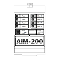
Displaying the Status of Addressable Modules
After the AIM-200 has stepped through all detectors, it will begin displaying all modules.
The digital display will repeatedly flash between the address and type/status of the module
assigned to the lowest address. The user can scroll through all modules using the
STEP-FORWARD and STEP-REVERSE switches. The SKIP switch advances through ad-
dresses rapidly.
Module Device Type/Status
The Device Type/Status field displays two characters for modules, outlined below.
Table 4-4: Device Type/Status Field Characters
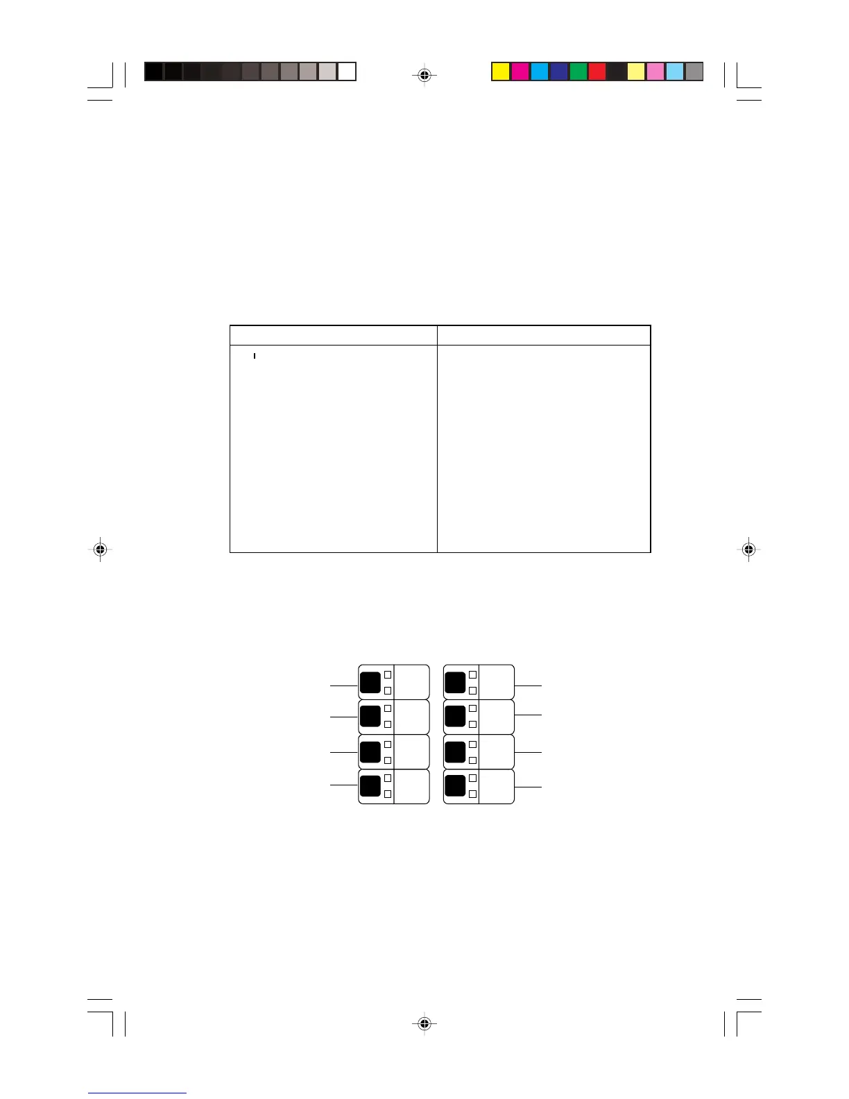
Advancing to an Address Range
By pressing any one of Zone Switches 1 through 8, the operator can advance directly to a
desired range of addresses. The AIM-200 will jump to the lowest address of a programmed
device within that range. The STEP-FORWARD and STEP-REVERSE switches can be
used to move to devices within each range.
code5
2
0
1
3
4
6
7
5
8
9
Address
Range
01-19
20-29
30-39
40-49
50-59
60-69
70-79
80-99
Display Status Tips:
1. To view module status directly upon entering Display Status mode, press the switch on
Zone 8 and advance through devices 80-99 (if present). The AIM-200 will begin display-
ing modules directly after the last detector.
2. The STEP-REVERSE switch can be used to back into a lower address range. For ex-
ample, to view the status of a device with Address “39,” press the switch for Zone 4, then
press the STEP-REVERSE switch once.
50-59
60-69
70-79
80-99
01-19
20-29
30-39
40-49
Left Digit Right Digit
C = Monitor Module or Pull Station Blank = Indicating circuit selected
C = Control Module A = Alarm
F = Fault--Trouble (open monitor module
zone; open or short CMX-1)
d = Disabled
O = Open (Form-C)
C = Closed (Form-C)
E = Error--No response from a device
(the AIM-200 is programmed for a
device that is in trouble or not
physically installed on the loop).
Technical Manuals Online! - http://www.tech-man.com