22
Document 15949 Rev. E 4/12/95 P/N 15949:E
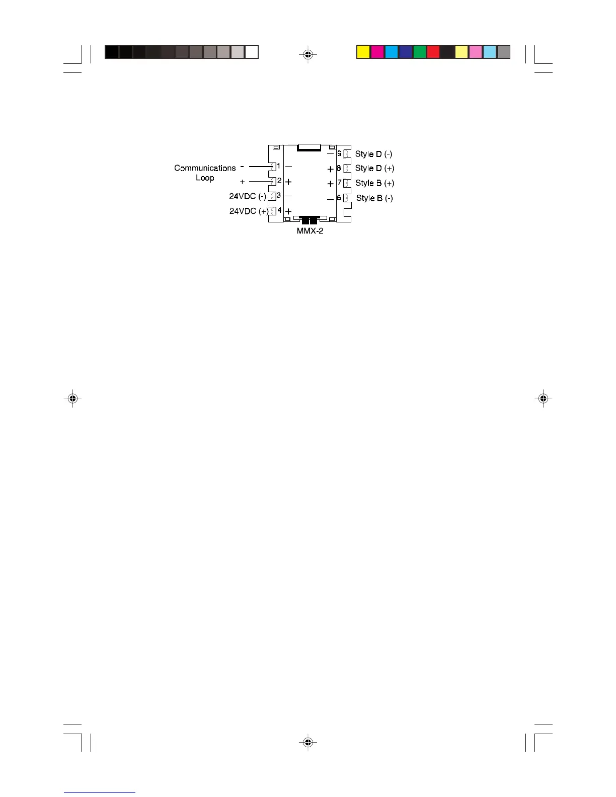
3.5 The MMX-2 Monitor Module
The MMX-2 monitor module is an addressable module that monitors conventional two-wire
smoke detectors. The supervised MMX-2 circuit can be wired as an NFPA Style B or Style
D initiating device circuit. Refer to the Device Compatibility Document for the type and
number of detectors the MMX-2 will support. Refer to Figures 3-13B and 3-14B for
MMX-2 wiring diagrams.
Communications Loop Connections
Connect the communications loop to MMX-2 Terminals 1(-) and 2 (+). The MMX-2 occupies
one module address on the loop. Set the rotary switches on the MMX-2 to the particular
loop address required.
NFPA Style B Initiating Device Circuit
Connect the alarm initiating devices to a single two-wire circuit. This circuit cannot be T-tapped
or branched in any fashion, and must be terminated across the last device by a listed 3.9K
ELR. Connect the circuit to MMX-2 Terminals 6 (-) and 7 (+). The maximum initiating device
circuit resistance is 25 ohms.
NFPA Style D Initiating Device Circuit
Connect the alarm initiating devices to a single four-wire circuit. This circuit cannot be
T-tapped or branched in any fashion. No external ELR is required for Style D wiring. Con-
nect the four-wire circuit to MMX-2 Terminals 6 (-) and 9 (-), then 7 (+) and 8 (+). The
maximum initiating device circuit resistance is 25 ohms.
Power
The MMX-2 requires connection of 24 VDC filtered, power limited, regulated and resettable
power on terminals 3 (-) and 4(+). Maximum stand-by current for two-wire detectors is
2.4mA. Maximum alarm current is 90mA.
Technical Manuals Online! - http://www.tech-man.com