21
Document 15949 Rev. E 4/12/95 P/N 15949:E
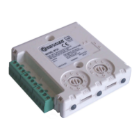
3.4 The MMX-1 Monitor Module
The MMX-1 monitor module is an addressable module that monitors normally open con-
tacts, shorting type alarm initiating devices. The supervised MMX-1 circuit can be wired as
an NFPA Style B or Style D initiating device circuit. There is no limit to the number of contact
type devices installed on a monitor module circuit. Refer to Figures 3-13A and
3-14A for MMX-1 wiring diagrams.
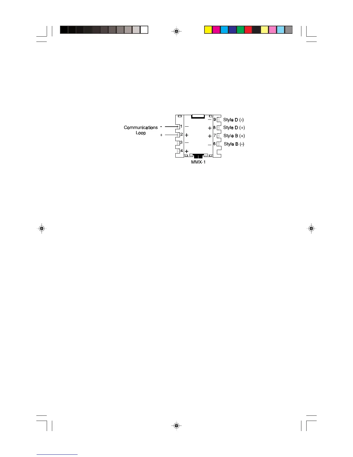
Communications Loop Connections
Connect the communications loop to MMX-1 Terminals 1(-) and 2 (+). The MMX-1 occupies
one module address on the loop. Set the rotary switches on the MMX-1 to the particular
loop address required.
NFPA Style B Initiating Device Circuit
Connect the normally open contacts of the alarm initiating devices to a single two-wire
circuit. This circuit cannot be T-tapped or branched in any fashion, and must be terminated
across the last device by a listed 47K, 1/2 watt ELR (Part No. A2143-00, supplied with mod-
ule). Connect the circuit to MMX-1 Terminals 6 (-) and 7 (+).
NFPA Style D Initiating Device Circuit
Connect the normally open contacts of the alarm initiating devices to a single four-wire
circuit. This circuit cannot be T-Tapped or branched in any fashion. No external ELR is
required for Style D wiring. Connect the four-wire circuit to MMX-1 Terminals 6 (-) and
9 (-), then 7 (+) and 8 (+). The maximum initiating device circuit resistance is 20 ohms.
Technical Manuals Online! - http://www.tech-man.com