46
Document 15949 Rev. E 4/12/95 P/N 15949:E
Section Five: Operating the AIM-200
5.1 Zone Display
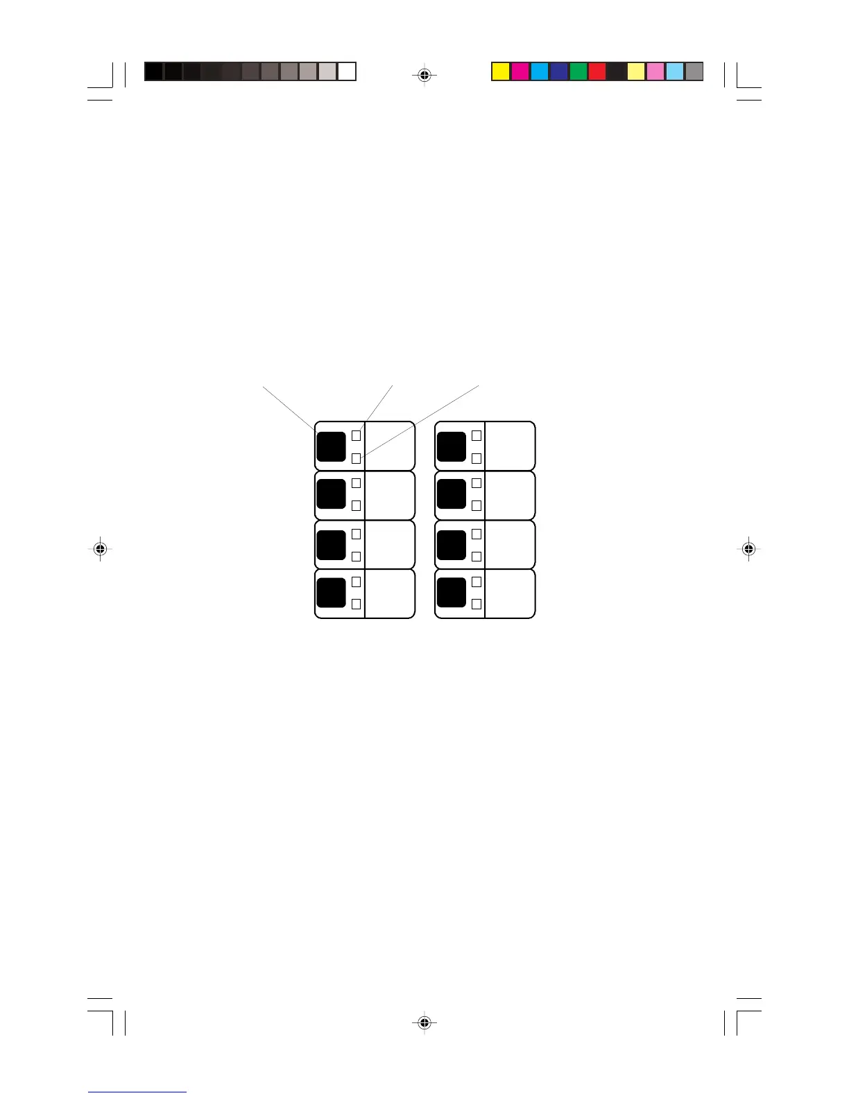
For each of the eight zone displays, a red LED, yellow LED and a switch are provided. The
198-point capacity of the AIM-200 is assigned to these zones using a “mapping” technique.
Each of the 198 devices may be mapped to one or more zones. If an initiating device
mapped to more than one zone is alarmed, all mapped zones will be placed into alarm. This
type of zoning could be used to provide a matrix, where one zone indicates the area and
another the type of device. For example, four zones could be used to indicate floor of alarm,
and three zones could be used to indicate smoke alarm, manual station, and waterflow
alarm. The eighth zone could be used for supervisory devices (the supervisory devices
would not be mapped into a floor zone).
CMX-2 Control Modules are activated by the AIM-200 when the zone that they are mapped
to enters an alarm condition. If a CMX-2 is mapped to more than one zone, it will be acti-
vated when any of the zones are in alarm.
The zone LEDs and switches emulate the functions of an IZM-8 module except when in
Program/Display mode. Pressing the switch in Program/Display mode displays all output
circuits in the system that are mapped to that zone.
The AIM-200 zone assumes the status of any device mapped to that zone that enters an
alarm or trouble condition. If any of the initiating devices are in alarm, the zone is reported
in alarm. If one or more devices (including CMX-2 modules) are in trouble, and no alarms
exist, trouble is reported for the zone.
One trouble condition, called “Maintenance Alert,” will be reported for analog detectors that
give readings in the 0-19% or 80-99% range. This trouble condition will result only if the
detector remains at this value continuously for 24 hours (smoldering fires could linger here
before passing 100%). After the detector remains at this level for about 24 hours, trouble is
reported for that detector.
code5
2
0
1
3
4
6
7
5
8
9
Display Program Switch
Alarm LED (red) Trouble LED (yellow)
Technical Manuals Online! - http://www.tech-man.com