10
Document 15949 Rev. E 4/12/95 P/N 15949:E
aim200-3
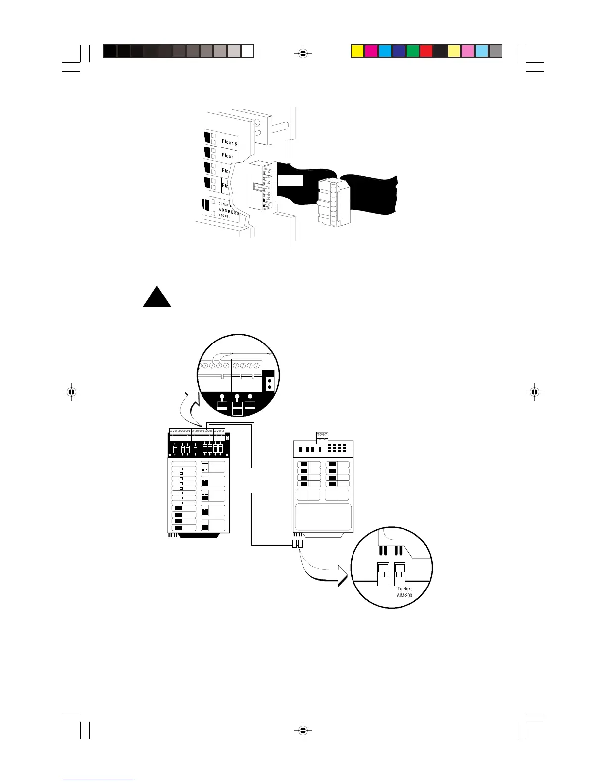
FC-2000 1st Row or
Expander Ribbon Cable
To Next
Module
From
CPU-2000
AIM-200
Figure 3-2: Connecting the Ribbon Cable
!
CAUTION: Do not connect any other device or circuit to the alarm
relay contacts on the CPU-5000 while the alarm bus cable (Part No.
71033) is installed in the system.
FC-2000
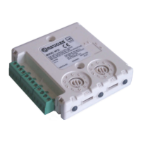
AIM-200
AIM-200
aimalrm
Alarm Bus
Cable
Part No. 71033
2 13 14 15 16 17 18 19 20
To First AIM-200
From
CPU-2000
To Next
AIM-200
Figure 3-3: Connecting the Alarm Bus Cable
Note: Refer to the System 5000 manual for power limited wiring requirements, document
number 15583.
From
CPU-5000
CPU-5000 1st Row or
Expander Ribbon Cable
CPU-5000
From
CPU-5000
Technical Manuals Online! - http://www.tech-man.com