3-3
3 Implementation
3. Implementation
3.2.2 ESM Fluid Line Details
The table below details the different lines of tubing that comprise the ESM External
Tubing Set (PN 59209). It should be noted that there is a single part number for the ESM
Tubing Set, whether it is to be installed on an ESM15 or ESM250. The FLEX2 + ESM
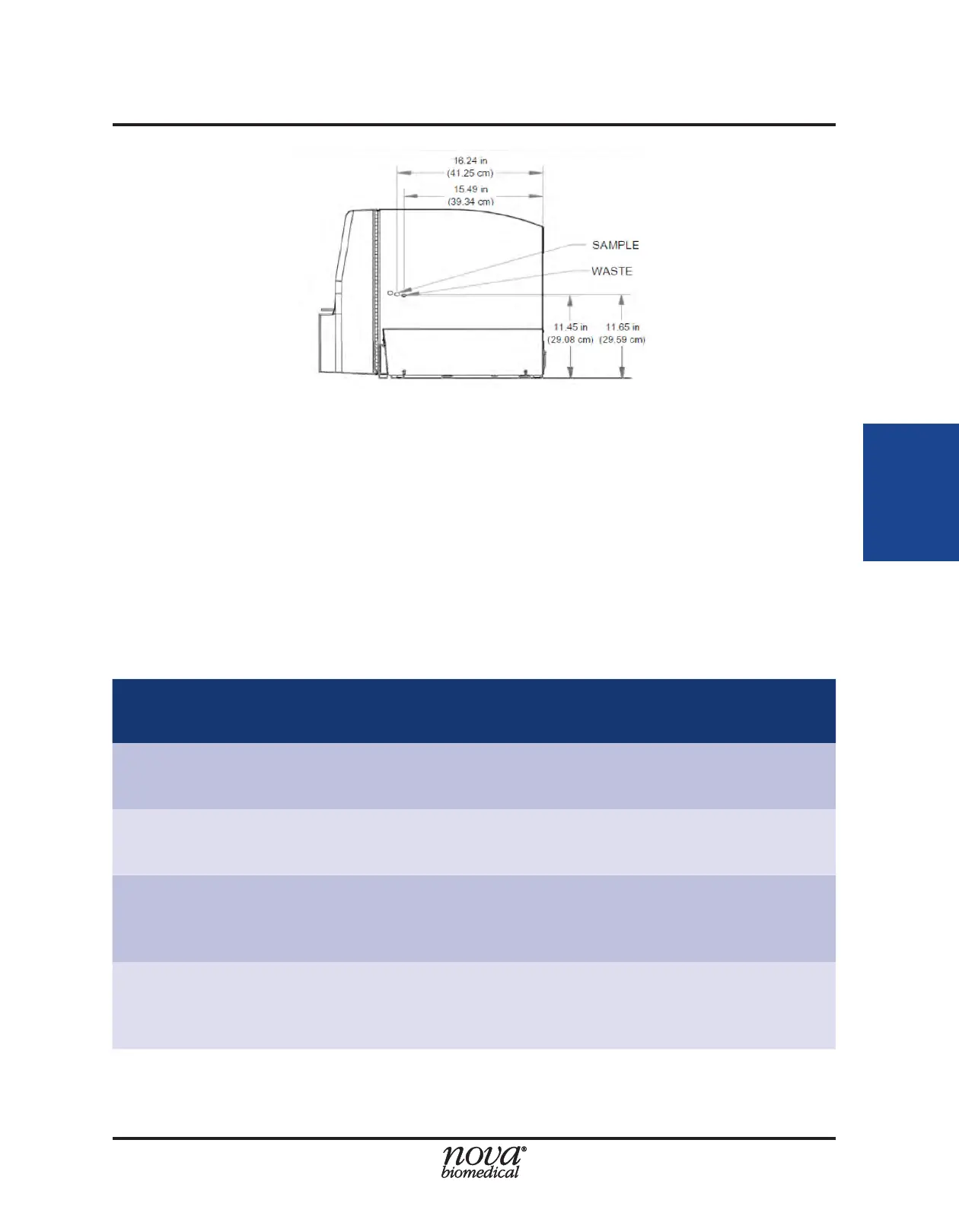
must sit directly to the left of the ambr®; and their positioning in relation to the ambr® is
restricted by the lines in red. The FLEX2 and ESM must be close enough together such
that the Waste (EF) line is not under strain, and the FLEX2 must be close enough to the
ambr® such that the Sample (CF) line is not under strain.
Table 3.2 ESM Fluid Line Details
Tubing Line Length Connection Function
Sample (CF) 36 in. (91.4 cm)
Right side of FLEX2 cover to
ESM Sample Cup (mounted
on ambr® deck)
Drains contents of Sample
Cup and delivers it to FLEX2
for analysis
Waste (EF) 22 in. (55.9 cm)
Right side of FLEX2 Cover
to ESM Syringe Pump
Evacuates sample waste
from FLEX2 + ESM flowpath
Cup Wash (CW) 48 in. (121.9 cm)
ESM Syringe Pump to spout
on ESM Sample Cup
Delivers fluid from ESM
Reagent Cartridge to
Sample Cup for priming and
cleaning
Performance Check (PC) 48 in. (121.9 cm)
ESM Syringe Pump to spout
on ESM Sample Cup
Delivers PC solution from
ESM Reagent Cartridge to
Sample cup for analysis by
the FLEX2
Figure 3.3 Right Side View- FLEX2 + Osm + ESM