3-4
BioProfile FLEX2 ESM Instructions for Use Manual
3.2.3 ESM15/ambr® 15 Spatial Requirements
The FLEX2 and ESM15 must be placed on a surface to the left of the ambr® 15 system.
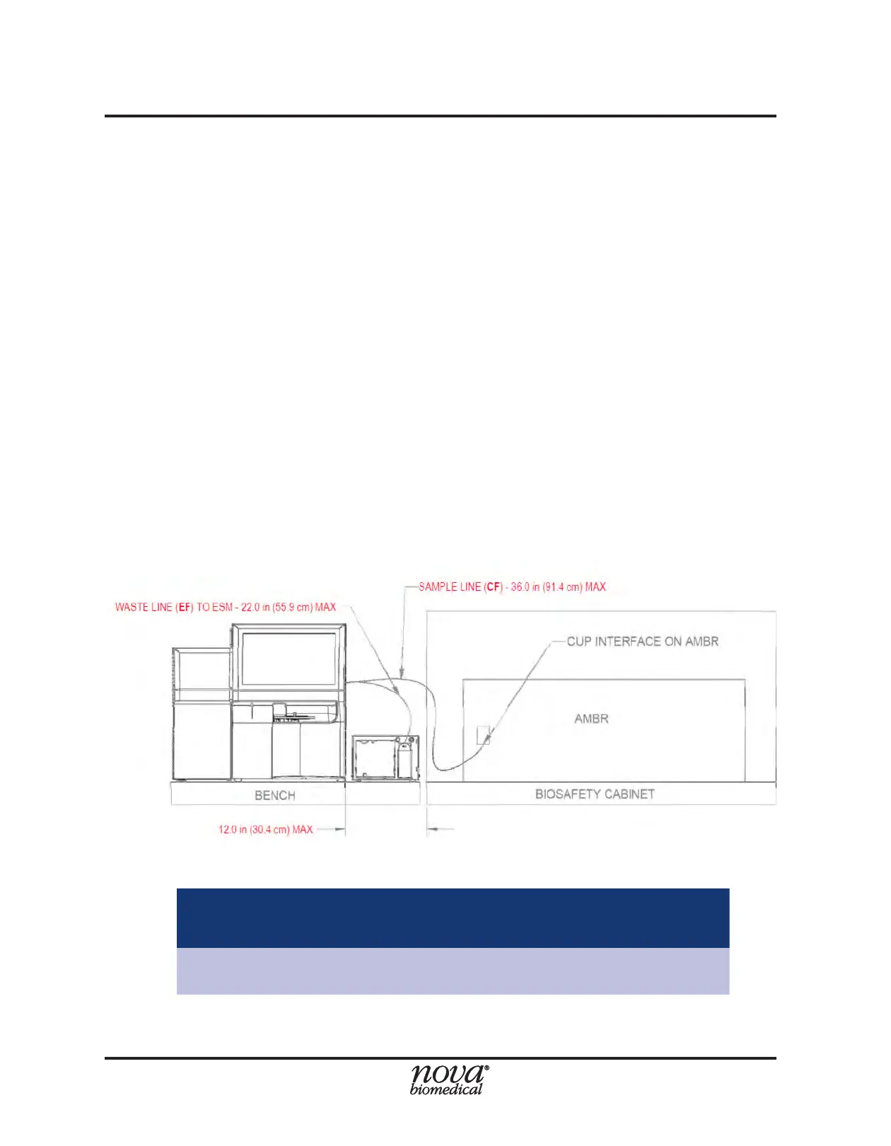
The maximum distance the FLEX2 can reside from the ambr® is constrained by the
sample (CF) tubing line which runs from the base of the sample cup to the right-side
cover of the FLEX2. The FLEX2 + ESM must be close enough together such that the
waste (EF) tubing line, which runs from the FLEX2 right side cover to the ESM syringe
pump, is not stretched or crimped. If the ambr® resides inside a laminar ow hood or
biosafety cabinet (BSC), the ambr® should reside as close to the left side wall as space
will allow. Additionally, it is recommended that any valves or other protruding structures
on the left side BSC wall be removed or relocated, as they may interfere with placement
of the ambr® 15 and proper routing of the ESM tubing lines. The estimated bench space
needed to the left of the ambr® 15 for the FLEX2 + ESM15 is provided in Tables 3.3 and
3.4, and accounts for ESM positioning, FLEX2 ventilation, and FLEX2 front panel door
and Osmo door clearance (when applicable).
The FLEX2 + ESM15 components should be arranged on the bench top to the left of
the ambr® according to one of the following options:
● Option 1 – ESM placed between FLEX2 and ambr®.
○ Ensure the right side of the FLEX2 resides no further than 12.0 in (30.4 cm)
from the left outer wall of the BSC.
Table 3.3 Estimated Bench Space Required (Left of ambr® 15)- Option 1
Configuration FLEX2 w/o Osmo FLEX2 + Osmo
ESM next to FLEX2
Inches (centimeters)
34.8W x 31.0D x 29.4H
(88.4W x 78.8D x 74.7H)
42.6W x 31.0D x 29.4H
(117.4W x 78.8D x 74.7H)
Figure 3.4 Option 1: ESM Between FLEX2 & ambr®