OEM617D Technical Specifications Appendix C
OEM6 Family Installation and Operation User Manual Rev 12 143
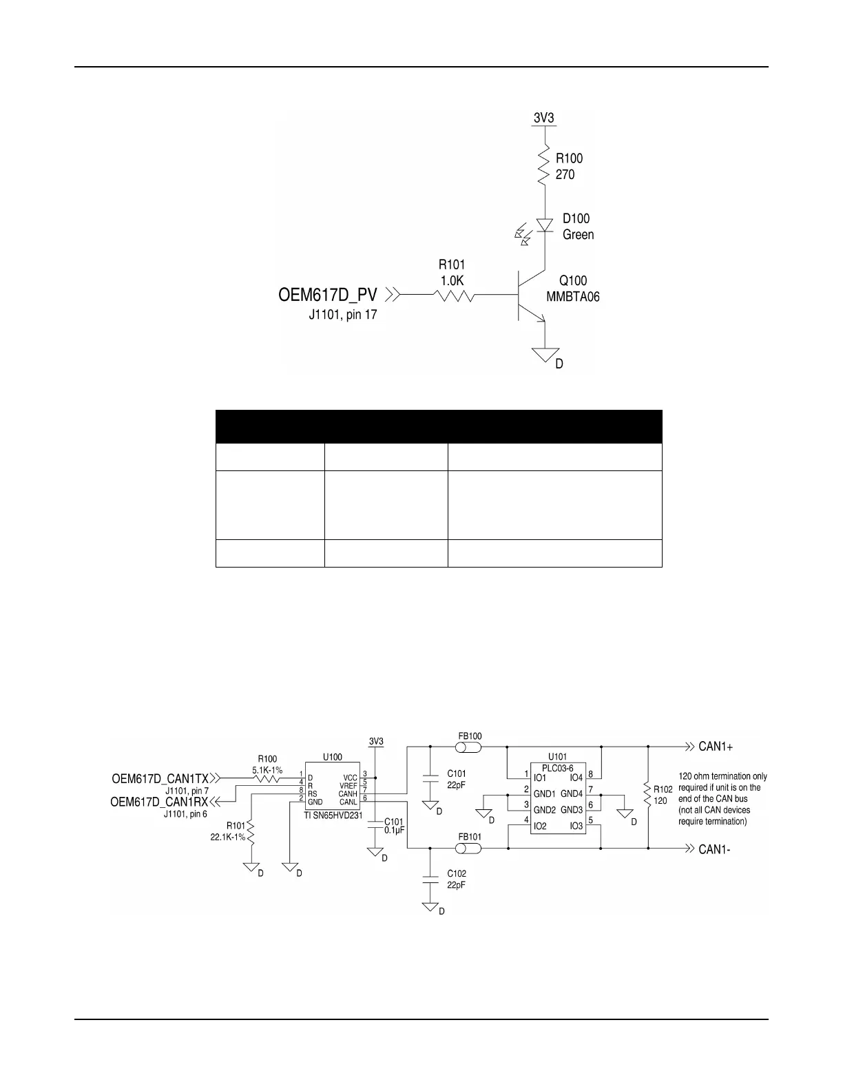
Figure 71: OEM617D PV LED Drive Buffer Schematic
Table 27: Bill of Materials (critical components)
C.1.3 CAN Interface
The OEM617D provides two 2.7 V (3.3 V-compatible) CMOS-level CAN controller ports. An external
transceiver is required. The following figure shows a typical CAN transceiver implementation.
The combination of ferrite beads and small value capacitors are not necessarily required but may provide
improved EMI performance. A low capacitance TVS device provides ESD protection.
Figure 72: OEM617D CAN Transceiver Implementation Schematic
Only use a 120 termination resistor when the CAN device is used at one end of the CAN bus. Multiple
terminations along the length of the CAN bus will degrade performance for all CAN devices on the bus.
Designator Manufacturer Manufacturer Part Number
FB100, FB101 TDK MMZ1005B800C
U101
Semtech
Bourns
OnSemi
LC03-6.TBT
CDNBS08-PLC03-6
LC03-6R2G
C101, C102 various (22 pF 5% 50 V COG 0603)