Operation OEM6 Cards and Enclosures Chapter 4
OEM6 Family Installation and Operation User Manual Rev 12 76
The LED blinks green on and off, approximately once per second, to indicate normal operation. If the
indicator is red, the receiver is not working properly. The indicator’s operation is described in Chapter 5, Built-
In Status Tests on page 81.
4.10.5 External Oscillator
For applications requiring greater precision than what is possible using the on-board Voltage Controlled,
Temperature Compensated Crystal Oscillator (VCTCXO), the OEM628 or OEM638 may need to be
connected to an external, high stability oscillator, at 5 MHz or 10 MHz.
Connect a cable from the external oscillator to the receiver’s external oscillator input connector. For the
OEM628 and OEM638, a MMCX female connector (J101) is used as shown in Figure 13, OEM628
Connector and Indicator Locations on page 37 and Figure 14, OEM638 Connector and Indicator Locations
on page 38. The receiver does not have to be powered down during this operation. However, if handling a
card directly, observe anti-static practices. The OEM628 and OEM638 input impedance is 50 ohms.
When the external oscillator is installed, use the EXTERNALCLOCK command (refer to the OEM6 Family
Firmware Reference Manual (OM-20000129) for details) to set the clock type (e.g: cesium, rubidium or
ovenized crystal) and frequency.
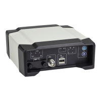
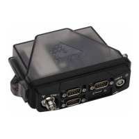
Refer to Table 6, FlexPak6 Status Indicators and Connector Labels on page 49 and Table 7,
FlexPak6D Status Indicators and Connector Labels on page 50 for details.
The OEM615, OEM617, OEM617D, FlexPak6 and FlexPak6D do not have an external
oscillator connection.