Revision 1.03
2-4 ChannelMaster TX7 Transmitter
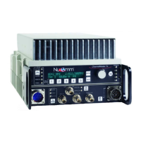
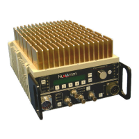
2.3 System Chassis Features
The ChannelMaster TX7 features a ro-
bust, weather-resistant housing design
to withstand rough handling in the field.
The ChannelMaster TX7 includes video
and audio processing boards, power
supply, 70 MHz modulator, power ampli-
fier, up-converter, and low noise fre-
quency synthesizer enclosed in a rug-
ged enclosure, with all input jacks and
user interface controls on the front
panel. The system chassis is typically
tripod mounted during use.
2.4 User Interface Overview
The user interface is conveniently lo-
cated on the front panel, and has three
elements:
1. A menu list for changing system
setup configuration options.
2. Preset buttons which can be
used to quickly change between
setup configurations.
3. Pushbuttons for operating com-
monly used controls (e.g. Digi-
tal/Analog and Transmit Mode).
2.5 Standby Mode
In the Standby mode, the ChannelMas-
ter TX7 is powered on, but the RF out-
put is muted, enabling the transmitter to
be tuned safely without radiating off-
frequency emissions. The ChannelMas-
ter TX7 will remain in Standby until on-
frequency lock has been obtained.
Switching from Standby to Normal mode
results in instantaneous on-frequency
transmission.
2.6 Video Signal Encoding
The CMTX7 features a built-in MPEG2
compliant digital encoder which trans-
forms Composite Video and SDI inputs
into the MPEG2 format. The ASI input
and optional Firewire are already in
MPEG2 format.
Optionally, the MPEG2 encoded signals
can be routed to an ASI output jack.
Signals from the MPEG2 encoder, the
ASI input, or the optional Firewire digital
video input can be digitally modulated
for transmission using the system’s
available digital modulation modes.
2.7 Audio Sub Carriers
Two (four optional) field programmable
synthesized audio sub-carriers feature
individual LINE, MIC, AES,
EMBEDDED, and TONE source selec-
tion (plus an OFF setting), and auto-
matic gain control (AGC). The sub-
carrier frequencies, Mode, and addi-
tional gain are front panel adjustable us-
ing the LCD interface. In the model with
optional XLR connectors, the right XLR
jack can be used as a microphone input
with or without 10 Volt phantom power.
2.8 Multi-Mode Modulator
The table below summarizes the modu-
lation types available.
Modulation
Mode
Name Modulation
Technique
1 COFDM Digital
2
Analog
FM
Analog
3 VSB Digital