Revision 1.03
Installation 4-3
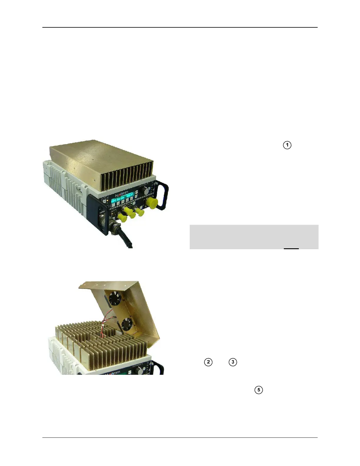
The unit has a large heatsink on its top
surface. This area requires clearance
from other objects while using the unit
within the unit’s normal operating air
temperature range.
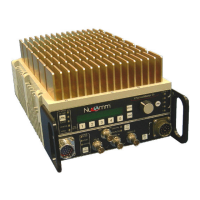
Some units have a shroud covering the
heatsink. (see Figure 4-3). The shroud
includes two built in cooling fans (see
figure 4-4).
Figure 4-3: CMTX7 Unit with Shroud
Figure 4-4: CMTX7 Unit with Shroud
(Shows Built-in Cooling Fans)
4.4 Electrical Installation
The unit front and back panels are
shown in Figure 4-5 thru Figure 4-7.
4.5 Power Connection
The built-in power supply accepts these
input voltages without requiring any
jumper or switch settings:
• 90 to 132VAC, 60 Hz
• 180 to 264VAC, 50 Hz
• +11 to +32VDC
The power input is labeled in Fig-
ures 4-5 and 4-6. The Power Pin-Outs
and Cable are illustrated in Figures 4-8
and 4-9. See Chapter 3 for the Power
Supply Specifications.
Nucomm ships a DC cable and the ap-
propriate local AC line cord. Alternate
line cords are available upon request.
Optional "Standby" Power feature:
For power redundancy, the unit can be
configured to accept both AC AND DC.
4.6 ASI, SDI, Composite &
70MHz Ports
All video inputs are made via 75 Ω BNC
coaxial cables to the appropriate, clearly
marked, front panel port. See Figures 4-
5 and 4-6.
ASI and SDI Inputs can be SD (NTSC or
PAL) or HD Video transport streams.
ASI (to 31.66845 Mbps) or SDI signals
are input via the ASI IN or SDI IN ports;
see and .
Composite or Baseband video can be
input via VIDEO
IN . Note: On units
without a marked SDI IN port, SDI is in-
put via the VIDEO
IN port.